- INTRODUCTION
1.1 General Description
The continuity of electrical power is an essential requirement for critical load operations .The Uninterruptible Power System is designed to meet the user‘s need of present mini-computer, micro-computer and the equipment of office automation that make the UPS more compact and less noisy.
To choose the UPS as your equipment protector is a wise investment because it supplies reliable, pure and stable power at affordable price.
1.2 Five key features
- Compact size.
- Light weight, easy to transport and place. 3.Special airflow design to avoid dust
4.Front door installation and repairing. Considerate and user friendly design. 5.Green Power minimizes environment pollution.
1.3 Important Notices
To be sure that the UPS will be operated correctly, the following items should be noticed:
- Read instructions carefully before operating the 2.All operating instruction should be followed.
3.Be careful not to damage the UPS while transporting. 4.UPS power connect instruction should be followed.
- Please don‘t open the case to prevent
- If the UPS will be stored for long period, the battery must be charged once every 90
- Retain the load within the rating of UPS to prevent 8.Keep the manual for reference.
9.Handle unusual events according to the trouble-shooting guide. 10.Keep the UPS clean and dry.
2. FUNCTION
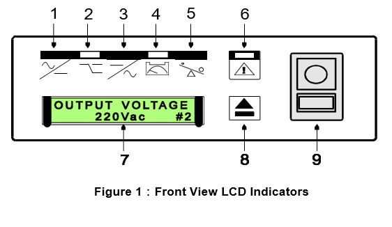
- Input LED : This indicates the incoming AC line is
- Bypass LED : This indicates the output outlet is supplied via bypass.
- Output LED : This means the UPS power is from its inverter to the
- Battery Capacity LED : The batteries are almost exhausted out.
- Overload LED : This indicates the UPS is connected with
- Fault LED : This indicates an UPS fault
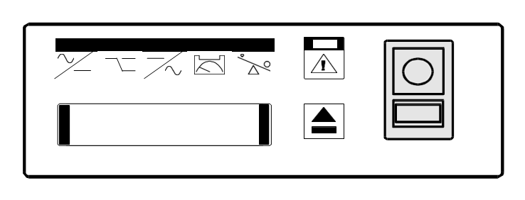
- LCD Display: This indicates digital signals.
- LCD Switch : This switch is pressed to select the UPS status on LCD
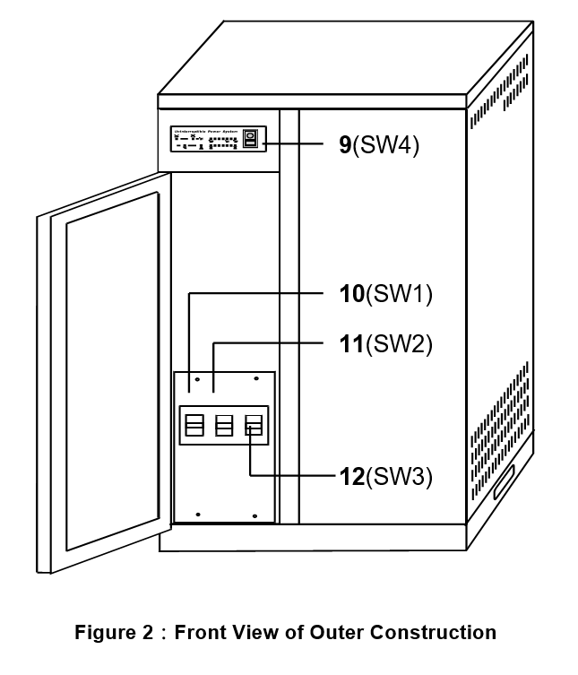
- PUSH ON-OFF Switch (SW4): To turn the UPS on or
- INPUT BREAKER (SW1): To control the AC input power.
- BYPASS BREAKER (SW2): To supply AC input power into Bypass output.
- BATTERY BANK BREAKER (SW3): To control external batteries.
- DB-9 Interface: Communication port between the UPS and computer.
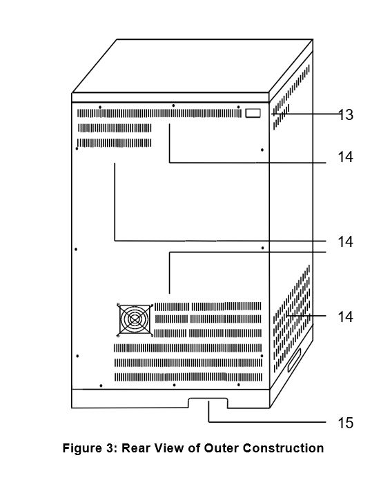
- Ventilation Holes: Please keep the ventilation holes free.
- Power Cords Holes: Input/output power cords and batteries power cords channel.
(1) UPS STATUS
AC: LOSS (OK) BAT: OK(LOW)
NO OUTPUT (BYPASS OUTPUT, INVERTER OUTPUT)
(2) INPUT VOLTAGE (5) OUTPUT FREQUENCY
(3) OUTPUT VOLTAGE (6) BATTERY VOLTAGE
(4) INPUT FREQUENCY (7) OUTPUT POWER
- LOCATION OF THE UPS
3.1 Transporting
- Disconnect all power cables if necessasry.
- Be careful not to damage the UPS while transporting
- 3.Don‘t move the UPS upside down.
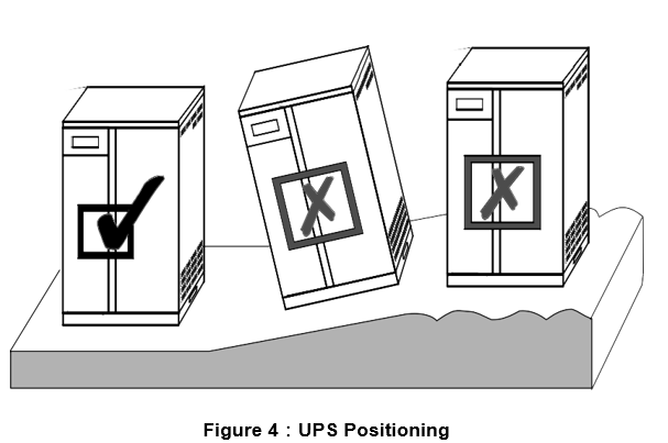
3.2 Positioning
- Do not put the UPS on rugged or declined surface. (Fig.4)
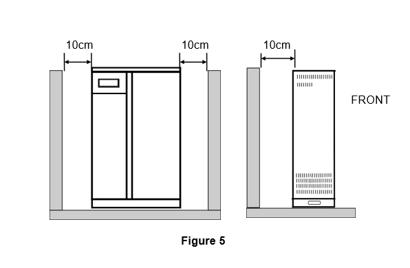
- Allow a minimum distance of 10 cm in the rear and two sides of the UPS for ventilation. (Fig.5)
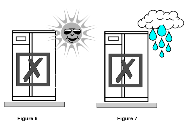
- Do not expose the UPS to direct sunlight or rain. (Fig. 6,7)
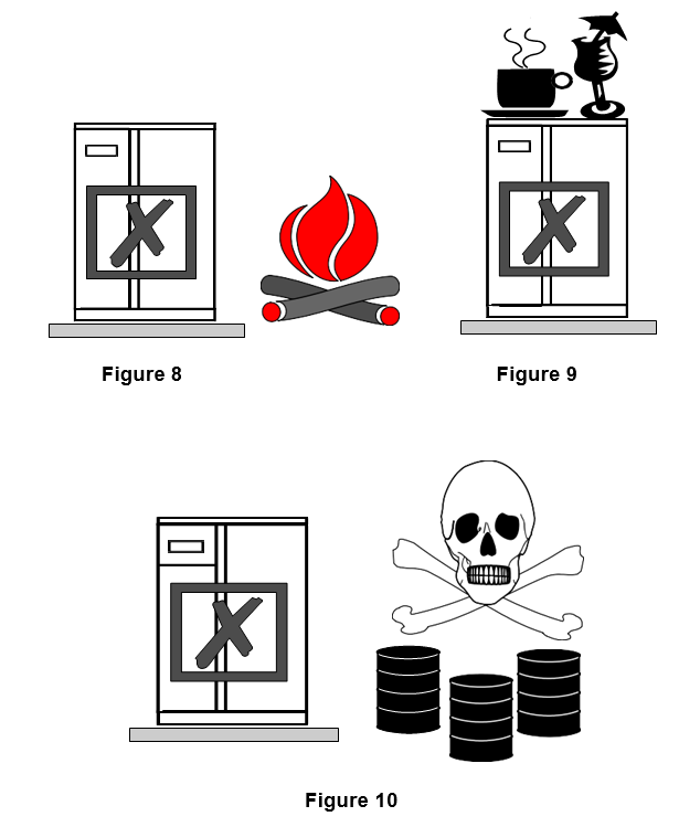
4. Keep the UPS far away from heat emitting (Fig.8)
5.Do not leave objects on the top of the UPS. (Fig.9)
6.Do not expose it to corrosive gas. (Fig.10)
7.Ambient temperature : 0℃ – 40℃
4. CABLE CONNECTION
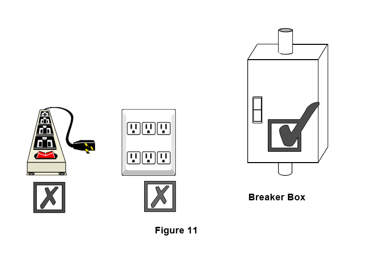
4.1 Caution
- Do not use household outlet (only 15A), because the outlet hasn’t sufficient capacity to support the
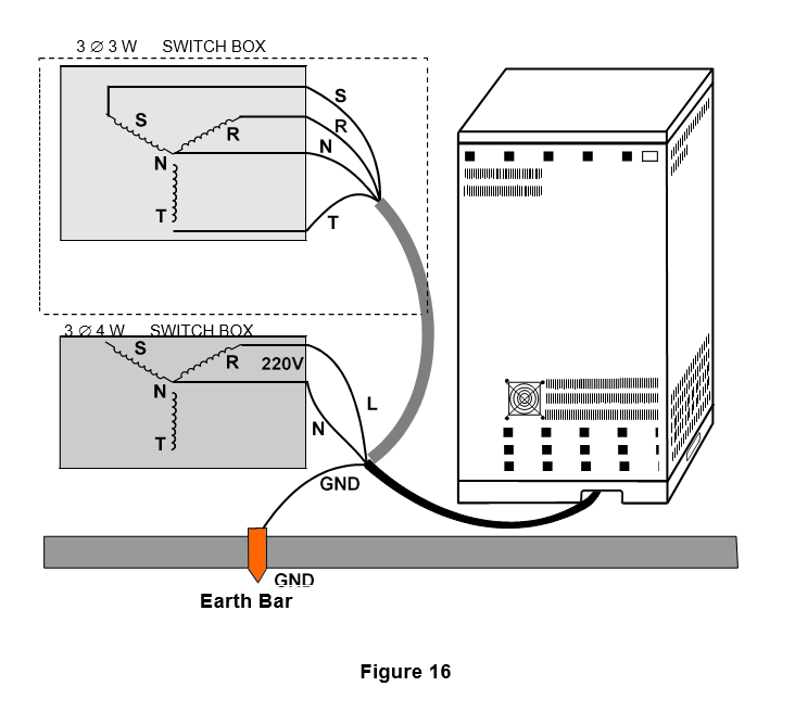
- Please connect the 220V power of nearest switch box to UPS input terminal block. (Fig.11)
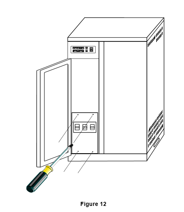
4.1 Power Supply Connection
- First, detach 4pcs screws on the rear panel with a screwdriver to find the terminal block. (Fig.12,13)
- Once power cords are connected, make sure all connectors are made properly and all the terminal block screws are tightened.
- The hole to insert input/output power cords is on below of the rear. Please connect power cords from the hole.
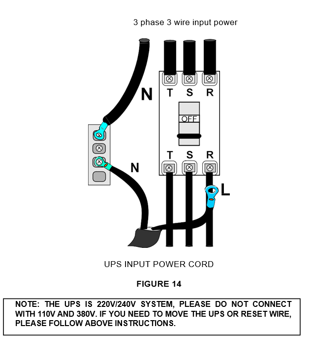
- Use power cables to connect the LINE(L), NEUTRAL(N) and GROUND(G) lines to the connector terminal
- The checklist of input current and input power cord is as below
MODEL
INPUT CURRENT
INPUT POWER CORD
10KVA
60A
22 ㎜ 2 (SOFT CORD)
8KVA
51A
22 ㎜ 2 (SOFT CORD)
7KVA
43A
14 ㎜ 2 (SOFT CORD)
5KVA
34A
5.5 ㎜ 2 (SOFT CORD)
- Once the input power cords are fixed, please check to confirm that the conductors are unable to contact with the case or other conductive material to avoid short circuit
- Please turn off AC supply to prevent short circuit while connecting line
-
Please follow an electrician law
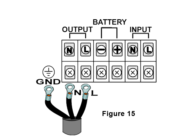
4.1 Output Connections
- Please refer to Fig.15 for connections
- Please follow load current design for output power cord
- Ensure the connected load doesn‘t exceed the capacity of the UPS
- The checklist of output current and output power cord is as below
MODEL
OUTPUT CURRENT
OUTPUT POWER CORD
TERMINAL
10KVA
46A
14 ㎜ 2
14-6
8KVA
37A
8 ㎜ 2
8-6
7KVA
32A
8 ㎜ 2
8-6
5KVA
22A
5.5 ㎜ 2
5.5-6
- Improper use of the grounding plug can result in a risk of electric shock. Consult a qualified electrician or serviceman if the grounding instructions are not completely understood.
- Please provide good grounding system.
- Please use the nearest point of earth bar or switch box for GROUND line.
5. OPERATION
5.1 Check Prior to Start Up
-
- Make sure the “Main Breaker” and “PUSH ON-OFF switch” are in the OFF
- Ensure the UPS is in a suitable location. (Refer to Fig.4-10)
- Check input cord is secured.
- Make sure the load is disconnected or in the “OFF” position.
- Check if input voltage meets the UPS requirement (220V ±10% ).
5.2 Initial Start Up Procedure
Please follow the instructions below to start the UPS. (Refer to Fig.1,2,3)
1. Be sure “Main Breaker” (SW1, SW2, SW3) and “PUSH ON-OFF switch”
(SW4) in the condition “OFF” and no load to be connected to output terminal of UPS.
2. Pull “Main Breaker” up to “ON” position; LED of “Input” and “Bypass”, should light up simultaneously.
3. Press “PUSH ON-OFF switch” to the position ” ON “, “LCD Display” shall light up immediately to indicate the AC utility power and batteries are normal. And the output outlet is supplied via bypass
4. About 20 seconds later, “Output LED” will also illuminate and “Bypass LED” fade out at the same time, indicating UPS is operating correctly. The UPS power is from its inverter to the load.
5. Disconnect AC input of UPS for blackout simulation, the “Input LED” will extinguish and UPS beeps every 4 seconds to remind user AC failure. This means UPS is in the condition of battery operation. The beep will stop automatically after 90 When approaching battery low level, UPS will beep every second for warning purposes.
6. Re-supply AC utility power, “Input LED” will light up again, then first installation is You can connect your equipping load into output terminal of UPS.
5.1 Normal Operation
Daily operation procedure:
Press “PUSH ON-OFF Switch (SW4)” to turn on or off the UPS.
5.2 Storage Instruction
- Turn off the UPS and “Main Breaker” if you will not use it for long period.
- If you do not use the UPS over 3 months, please follow initial start up procedure and keep supplying power to the UPS for at least 24 hours to ensure battery fully recharged.
6. TROUBLE SHOOTING GUIDE
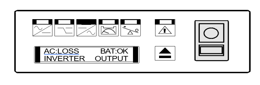
6.1 Symbol Reference
6.1 UPS Status and Action
The description of the following guideline may be helpful in problem solving.
1. LED STATUS as below:
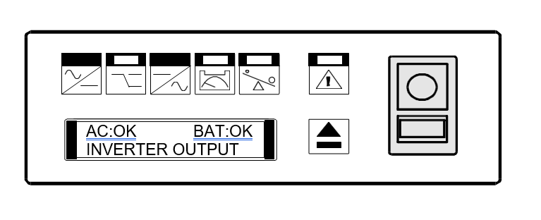
UPS STAUS:
AC utility power is normal, UPS is running normally with full load.
ACTION: No.
2. LED STATUS as below:
UPS STATUS:
AC utility power is normal, UPS is running normally. Batteries have been charged to 90% or more.
ACTION: No.
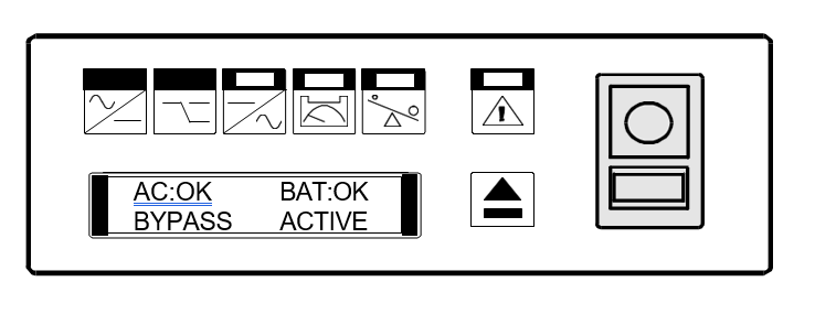
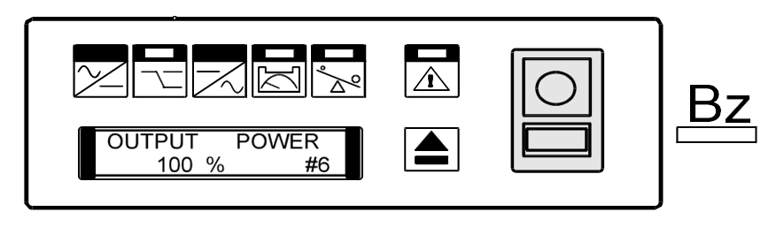
3. LED STATUS as below:
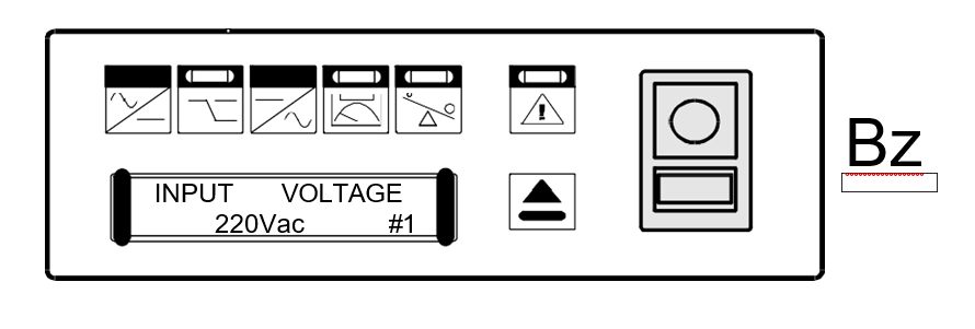
UPS STATUS:
AC utility power is 220V, UPS is running normally.
ACTION: No.
4. LED STATUS as below:
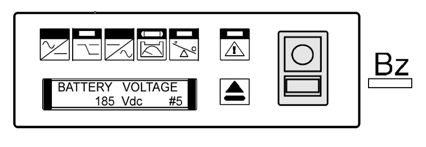
UPS STATUS:
AC utility power is normal. UPS is running normally, but battery capacity is low.
ACTION: Charger broke down. Please replace charger board.
5. LED STATUS as below:
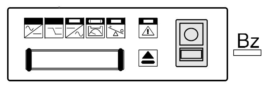
UPS STATUS:
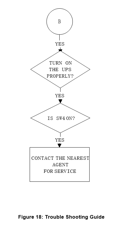
AC utility power is normal. The output load is supplied by utility power. If “PUSH ON-OFF Switch” is not on, UPS does not start up.
ACTION: Refer to flowchart Fig.18.
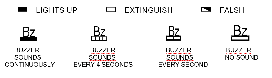
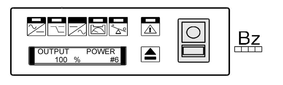
6. LED STATUS as below:
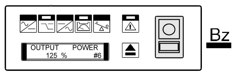
UPS STATUS:
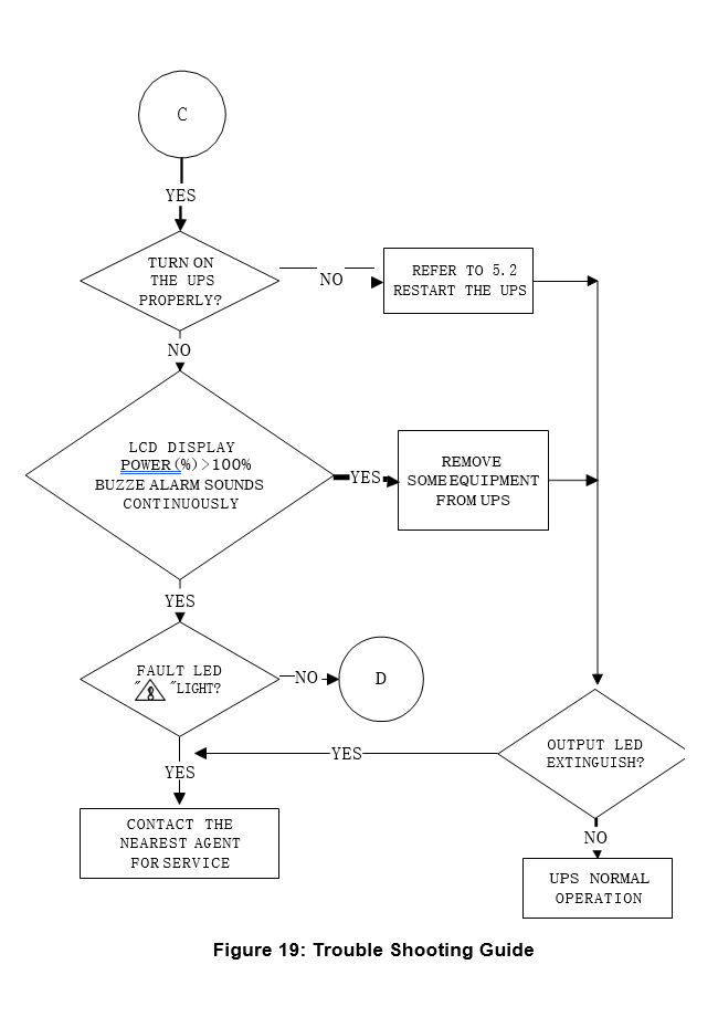
AC utility power is normal but UPS is overloaded. “Overload LED” lights up and buzzer beeps continuously.
ACTION: Please reduce the critical load to POWER(%)<100%. If the situation continues, Please refer to flowchart Fig.19.
7. LED STATUS as below:
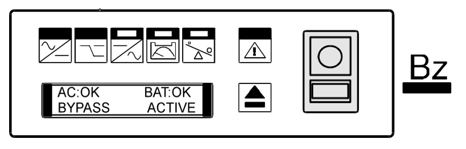
UPS STATUS:
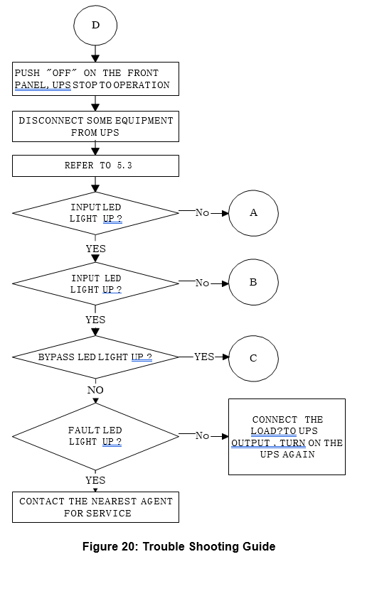
AC utility power is normal, but UPS is abnormal. The load is supplied by AC utility power via bypass.
ACTION: Refer to flowchart Fig.20.
8. LED STATUS as below:
UPS STATUS:
AC utility power fails .The load is supplied by battery power in UPS .The UPS is connected with full load. Buzzer alarm sounds every 4 seconds. ACTION: If AC utility power fails, reduce the less critical load in order to
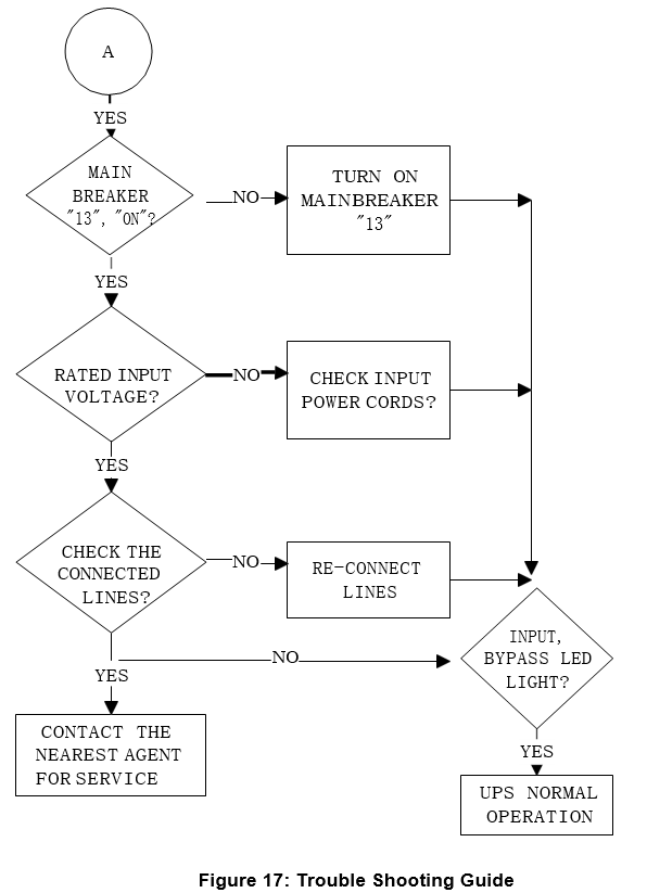
extend backup time. If it is not abnormal power failure, refer to flowchart Fig.17
9. LED STATUS as below:
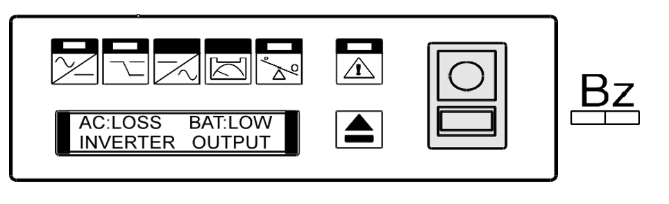
UPS STATUS:
AC utility power fails .The load is supplied by UPS, and battery power is running out. Buzzer alarm beeps every second.
ACTION: UPS will shut down automatically. Please save data soon.
10. LED STATUS as below:
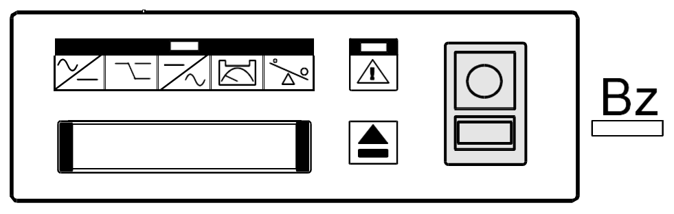
UPS STATUS:
AC utility power fails and battery runs out. UPS has shut down automatically.
ACTION: UPS will restart up when AC utility power is restored. If AC utility power failure is more than 6 hours, please follow storage instruction.
7. OPERATION MODES OF THE UPS
7.1. UPS System Block Diagram (Fig.21)
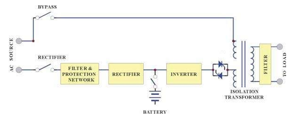
Figure 21: UPS System Block Diagram
7.2 Normal Operation (Fig.22)
There are two main loops when AC utility is normal: the AC loop and the battery charging loop. The AC output power comes from AC utility input and passes through AC/DC rectifier, DC/DC booster, DC/AC inverter and static switch to support power to load. The battery charging voltage comes from AC utility input and converted by AC/DC charger to support battery-charging power.
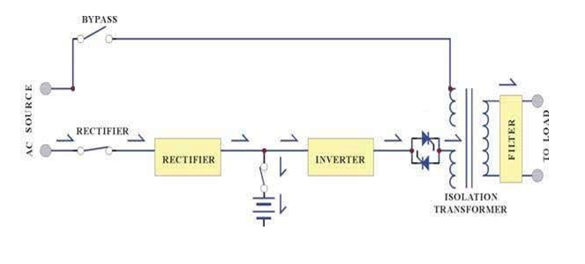
Figure 22: Show How UPS Works when AC Utility Supplies
7.3 AC Utility Failure (Fig.23)
The AC output comes from battery, passing through DC/DC converter, DC/AC inverter and static switch within the battery backup time.
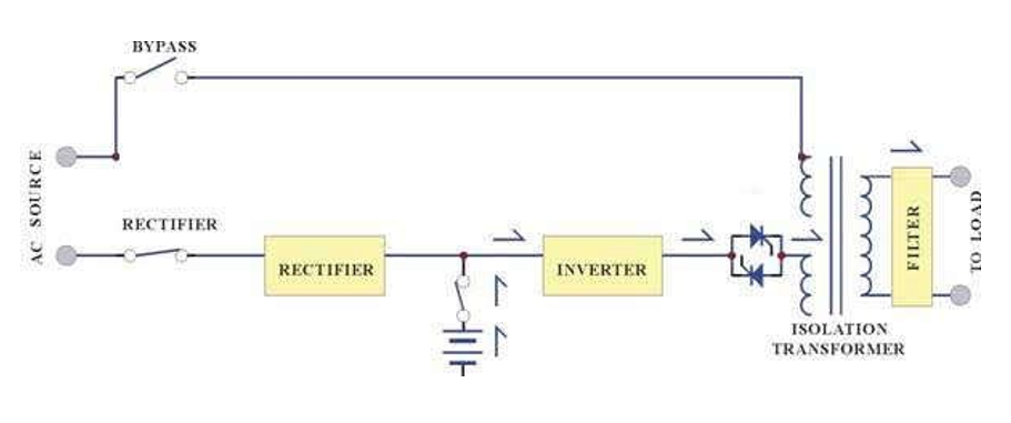
Figure 23: Show How UPS Works when AC Utility Fails.
7.4 Bypass Enable (Fig.24)
Under the following 5 conditions, the bypass will be enabled:
- Overload.
- Inverter failure.
- Inverter start initially (about 20 seconds).
- Turn off, SW4 is pressed.
- Over-temperature
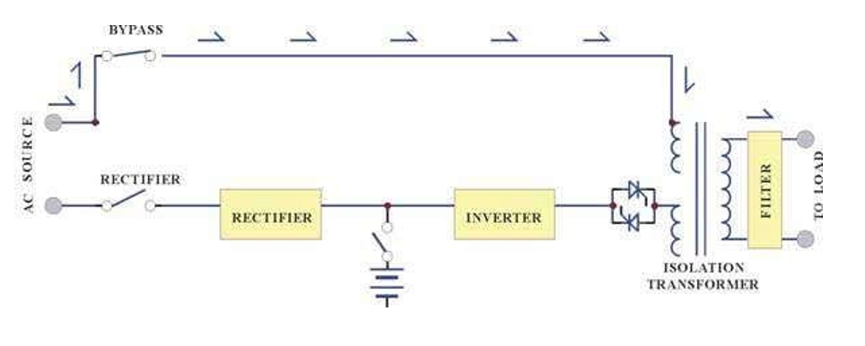
Figure 24: Show How UPS Works in Bypass Mode
7.5. Battery and Recharge
- UPS is “ON”, or Input breaker SW1, Battery breaker SW3, Bypass breaker SW2 are ON, batteries can be recharged automatically, and about 8-10 hours to 90% capacity
- Battery Back Up Time (Fig.25)
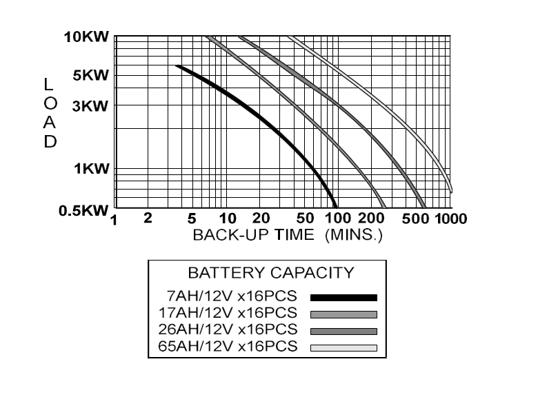
Figure 25: Battery Back Up Time
- Please contact the agent, if the external battery set is needed to extend the backup
-
- Please keep battery fully recharged to extend the battery
- There are no customer serviceable components inside, do not open the cover or attempt to serve the High voltage may remain when the unit shuts down.
- Please follow all operational
7.6 Daily Maintenance
- The environment in which the UPS is located must be kept dry and relatively dust free.
- The exterior panels can be cleaned with a mild cleaning solution.
- All power connections at the input, battery, output terminals and circuit breaker must be periodically checked every month.
- The battery cells used are the sealed maintenance-free The factory adjusts both charging voltage and current according to the battery specifications.
- If external battery is the vented lead-acid type, the electrolyte should be inspected every three months. If liquid level is below the low limit, pure water must be added to the battery cells.
8. COMPUTER INTERFACE
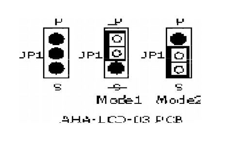
The communication interface (DB9 port) on the back of the UPS may be connected to a host computer. The port provides two different modes for communicating with the computer.
Mode 1: Supply RUPS monitoring and management software.
Mode 2: Supply RUPSII monitoring and management software (default).
8.1 DB9 PIN Assignment
1. Change to Mode 1 or Mode 2 of Method
Mode 1: Supply RUPS Monitoring And Management software
The port simulates relays closing to communicate with the computer. Its major functions are as follows.
- To broadcast a warning when power
- To close any open files before the battery exhausted
- To turn off the
Mode 2: Supply RUPSII Monitoring And Management software
The UPS communicates with the computer by sending out RS-232 data streams to one of the serial ports. By this method the user is able to monitor the following parameters.
|
Input Voltage |
Indicates the present input voltage to the UPS system when AC power is present. |
|
Output Voltage |
Indicates the present output voltage of the UPS. |
|
AC Frequency |
Indicates the actual output frequency of the UPS. |
|
Battery Voltage |
Indicates the present DC voltage of the UPS battery. |
|
Temperature |
Indicates the actual temperature inside the UPS. |
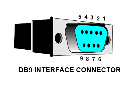
8.2 DB9 PIN Assignment
PIN 1: UPS Fault
PIN 2: AC POWER Failure PIN 3: Inverter Power On
PIN 4: Common GND of Pin 1,2,3,5,8 PIN 5: UPS Battery Low
PIN 6: Turn off UPS PIN 7: GND of PIN6
PIN 8: inverter Output PIN 9: RS232 TXD
8.3 Change to Mode 1 or Mode 2 of Method
Change JP1 Short-Jump according to your requirement.