CAUTION !
- Hazardous voltage exits inside the UPS (includes the connection terminals). Cable connection and maintenance should be done by professional or qualified personnel.
- The UPS has its own internal power source (batteries). The output terminals may be live even when the UPS is not connected to the AC supply.
- DC capacitors are employed in this unit. Hazardous voltage still exists even when the unit is not energized. Do not touch any part of the inside of the UPS.
WARNING !
- Be sure to operate the UPS within the rated power level.
- Prevent direct exposure to direct sunlight, rain or contaminating environment.
- Only qualified technicians should replace the batteries. Since batteries have high short-circuit current capacity, mistakes in connection or disconnection can cause severe burns or death to servicing personnel.
- SYSTEM OVERVIEW
1.1. Construction of the UPS
General Topology: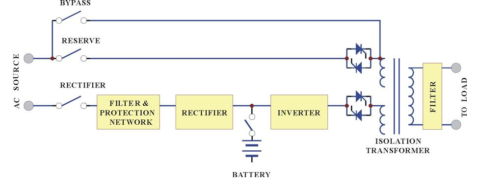
The UPS system is composed of input breakers, input filter & protection network, rectifier, battery bank, inverter, static switch, bypass breaker, isolation transformer and output filter. The basic topology is shown in the diagram above. Under normal AC mode, energy from the AC source is converted to DC power and supplied to the inverter to charge the batteries to its full capacity all the time, ready to support the output load in case of AC source failure.
Although the principle and operation of a UPS seems simple and straightforward, the requirement for a reliable and intelligent UPS makes the design and manufacturing of a high power UPS one requiring advanced technology, intelligence, experience and most important, consideration of the user interface. Many years have been spent in designing the most rugged, intelligent and reliable UPS for the market, and a safe and convenient UPS for the user.
Choosing the best and most suitable UPS for a given application can be easy or difficult, depending on the client’s knowledge of key parameters. The most obvious specification, output power, depends on the size of the load. Often, an allowance of 50% more power is added to the present load requirement, both for tolerance and for future expansion.
Another important issue is reliability. The prime aim of a UPS is to protect your load. Therefore, the UPS should be much more reliable than the AC source. An unreliable UPS may suffer the problem of frequent break down, even more frequent than AC failure, and the cost of repair may become more than the cost of the unit itself.
Generally, there are four different modes of operation, the NORMAL OPERATION MODE, the BACK-UP (BATTERY) MODE, the RESERVE MODE and the MAINTENANCE BYPASS MODE. These are explained below.
Normal Operation Mode: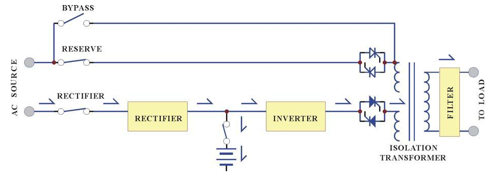
The rectifier converts the AC input to DC power to supply the inverter and charge the batteries simultaneously. All the fluctuations, surges and spikes of the AC input are removed during AC to DC conversion. Therefore, the AC supplied by the inverter is clean and stable.
Back-up Mode: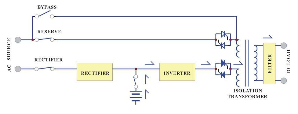
Since the batteries are connected directly to the DC bus, when the AC fails, the batteries change immediately from receiver to donor, supplying energy to the inverter instead of receiving energy from the rectifier. The output AC is not interrupted. Therefore, the load connected to the output is protected.
Reserve Mode:
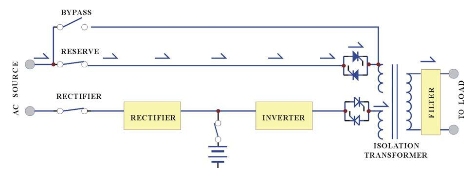
When the inverter is in an abnormal condition, such as over temperature, short circuit, abnormal output voltage or overloaded for a period exceeding the inverter’s limit, the inverter will automatically shut down in order to protect itself from damage. If the utility power is normal, the static switch shall transfer the load to the reserve source without interruption of AC output.
Maintenance Bypass Mode:
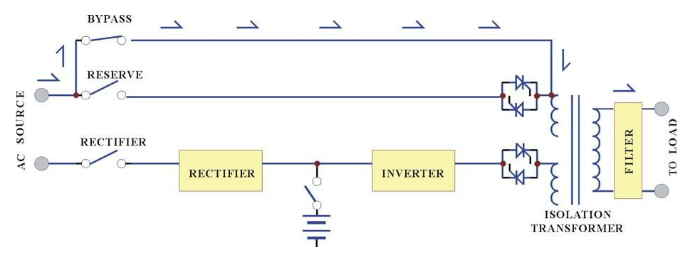
In case of UPS maintenance or battery replacement, and where the load cannot be interrupted, the user can turn off the inverter, close the bypass breaker and then open the rectifier and reserve breakers. The AC output will not be interrupted during manual bypass transfer procedure. Therefore, the maintenance bypass switch keeps continuously supplying power to the load. Electricity will not exist in UPS except the output transformer, thus ensuring the safety of service personnel.
Generally, the UPS is expected to run 24 Hours a day in normal operation mode once it is installed, except when the utility power fails, under overload conditions, or during maintenance.
Normal operation with batteries connected provides clean, stable, regulated and uninterrupted power to the load, free from any spikes and surges. Therefore, the UPS can be regarded as a perfect AC power source, limited in back-up time, under mains failure, only by the capacity of the batteries.
1.2. Features and Advantages
- Reliable input protection: Circuit breakers are placed in each individual input loop to ensure power can continue through another loop in case of breaker trip caused by an abnormal condition in either rectifier or load.
- Input surge protection: An MOV (surge protector) is added at the input, providing protection to both UPS and the load from any lightning surges, or surges caused by neighboring large loads.
- EMI suppression: An EMI filter is added to meet the international EMC limits. Therefore, very low noise is emitted, and no interference is supplied to other equipment connected to the same AC source.
- Ruggedness: The rectifier employs phase control technology to regulate the DC bus voltage. This is the most efficient method to charge the batteries. The SCR used are inherently rugged. Additionally, a large inductor is added at the input to avoid deforming the AC source waveform.
- High frequency design: The inverter uses high frequency, high efficiency IGBT, PWM methodology to convert the DC power to AC power. Therefore, the number of components is fewer, reliability is improved, and the size and weight of UPS is reduced, performance is improved, and acoustic noise is minimized.
- True Galvanic isolation: An isolation transformer is placed at the output. This can solve the problem of poor input grounding, can allow a different ground between input and output, can avoid the annoying problem of ground leakage current, and can be tied to any potential provided on site. The AC output is isolated under every mode of operation. Additionally, the user gets the bonus of attenuation of common mode noise from the output isolation transformer.
- Plug & Play Modular design: The power circuit is separated into several modules plugged into slots in the UPS, which are easy to pull out, permitting quick maintenance and easier trouble shooting.
- Cold start function: the UPS can be started without an AC source, that is, can be started with battery power only. This is possible because current limit circuitry is added, preventing the problem of large inrush current blowing the battery fuse and damaging the DC capacitors when batteries are connected to an empty DC bus (before the DC bus is energized).
- Multi-CPU design: Several CPUs are employed in the control circuit, and critical functions are designed with parallel redundancy to improve reliability. Therefore, in case of one CPU failure, the other CPUs keep the UPS operational, and the output AC is not affected.
- Protection against misuse: The UPS is designed with breaker on/off sensor, power supply sensor, etc. Therefore, any operational mistake made by the user causes no harm to the UPS.
- Accepts wide input range: The UPS is designed to accept a wide input range, so that it can work effectively under an unstable AC source. All of the input components used are specifically selected to handle extreme high voltage and high current.
- Operating environment: Each component of the UPS is chosen with large safety margin to accommodate extreme environments, such as temperature, humidity, altitude, shock or contamination.
- Intelligent charger: The UPS will automatically recharge (boost charge) the batteries every time the batteries are depleted to a voltage level equal to 2V/Cell. Thus, the batteries can be restored to full capacity as soon as possible, and made ready for the next back-up requirement. In order to keep the batteries in the best condition, the UPS will boost charge the batteries for several hours (selectable) automatically every month. To avoid over charging the batteries, boost charge will stop when the ambient temperature is over 35oC (95oF).
- Intelligent battery test: The batteries are tested after every boost (initiated by battery discharge or by the monthly boost charge cycle). This is done without interrupting the operation of the rectifier, preventing the risk of output AC failure in case of a bad battery. The user is informed of the battery condition, so that action can be taken before the full capacity of the batteries is needed.
- Huge charging power: The charging power is selectable (Lo/Me/Hi) according to Ah rating of the batteries, and can charge up battery banks providing more than 8Hrs back-up time without adding an extra charger.
- MTBF of fans are extended: Fans used to cool the UPS, are designed to slow down under light load, so that the life expectancy of the fans is extended beyond the normal.
- Redundant power supply: A supplemental power supply is added to provide redundancy for supplying power to the static switch, so that there will be AC output no matter what happens to the UPS.
- Variety of accessory (options): With built-in intelligent communication interface as well as output ports of RS-232, RS-485, and dry contacts, there are several options are hence available such as remote control panel, 3 phases software for PC monitoring, auto dialing module, battery monitoring module, 3 phases SNMP card, and emergent power off (EPO) switch. Please refer to the chapter 7 of options for details.
1.3. Rectifier
The main function of a rectifier is to convert the AC input to DC power, and supply it to the inverter. The inverter then converts the DC power to AC power for the load. The UPS use the DC power to charge the batteries as well, which is the most efficient method of charging.

UPSs in the sizes 10KVA to 100KVA use 6-pulse fully controlled rectification (optional 12-pulse). An inductor is added before the rectifier to improve the power factor, smooth the current waveform and eliminate the harmonic current. The control circuit regulates the DC bus within 1%. Soft walk-in circuitry (approximately 20sec.) and current limit circuitry is used to prevent over current or instantaneous surge current.
Extra under-voltage and over-voltage protections are added to improve reliability and to shutdown the rectifier in case of abnormal conditions. The DC bus is adjustable to fit different types of batteries. The power component used in the rectifier is specially selected to handle extreme high voltage and high current. The rectifier is designed to operate under a wide range of AC input, from 177 to 300VAC, to operate under the poor power conditions found in some areas.
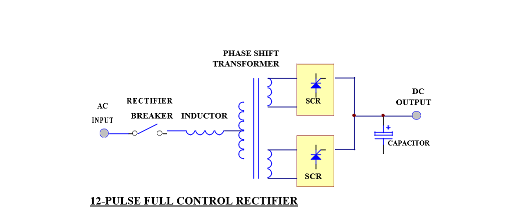
In order to further improve the power factor and reduce harmonic current drawn by the rectifier, UPS at 120KVA and above, use the 12-pulse full controlled rectifier. The total current harmonic current can be reduced to around 15%, and power factor improved to over 0.8. A phase shift transformer is added to achieve this performance. The input inductor is retained also to obtain the best result. Although this results in higher cost, the unit is much more reliable and rugged. Users do not need to increase the input breaker and cable sizes, since input KVA and harmonic current drawn is minimized, fulfilling the worldwide energy saving requirements.
The harmonic current can be further lowered by adding harmonic filters (factory installation available). The total harmonic current can be reduced to approximately 9%.
Another alternative method to reduce the harmonic current (especially for very large KVA UPS) is to employ 18-pulse full controlled rectifier (available as an option). The total harmonic current can be reduced to approximately 7%.
1.4. Inverter
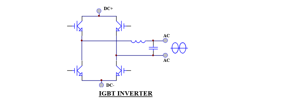
The inverter is composed of IGBT, inductor, capacitor, snubber, control circuitry and protection circuitry. The inverter converts the DC power from the DC bus to AC power to supply the output load. The UPS uses IGBT technology which switches at frequencies beyond the audible range, therefore producing no audible noise.
The UPS uses voltage regulation circuitry to limit the voltage variation within 1%. Special compensation circuitry is added to eliminate the output distortion. Every component is oversized to accept the wide DC input range (from 285 to 420VDC), so that the output waveform remains sinusoidal throughout the range. With the aid of dynamic feedback loop the inverter will keep a sine waveform even under non-linear load.
An independent inverter is used for each phase. Although it is more expensive, each inverter has its independent feedback, so that the voltage is unaffected when load is added to the adjacent phase, producing excellent voltage regulation under 100% unbalanced load.
The IGBT is operated in its optimal condition to obtain best efficiency, so as to minimize the power cost of the user.
Usually, the most frequent failures of the UPS occur at the inverter. Therefore, we have added redundant protection circuitry to protect the inverter. A strong snubber is added to suppress the spikes and noise, oversized, high quality components are used throughout, semi-conductor fuses are provided, and ventilation is maximized. The result of this design is a more rugged, reliable and high efficient inverter. At the same time, the inverter can sustain overload and high peak current drawn by the load. Additionally, a longer MTBF is achieved.
1.5. Static Switch

The static switch is composed of two pairs of SCRs, connected back-to-back. The switch can transfer the load from reserve to inverter or from inverter to reserve without losing power at the output. Therefore, it is a very important portion of a UPS.
Detection circuitry is added to the control circuit to achieve zero dead time transfer. Extra detection logic is employed to control when the static switch should transfer. For example, when output is short circuited, under normal mode operation, the UPS detects the short circuit and stops the inverter. The static switch will not transfer power to the reserve circuit, which might damage the reserve breaker. In case of an overload, the UPS will stop the inverter after a period the inverter can endure, and then transfer the load to the reserve circuit, since the overload capability of the static switch is higher than the inverter.
The transfer action is determined according to the reserve-input voltage and frequency to protect supplying incorrect power to the load. Finally, there is a double check by the CPU as to whether the transfer is successful or not.
1.6. Maintenance Bypass Switch
Unlike other UPS, the maintenance bypass switch is already installed inside the UPS for convenience. It should be open under normal operation, and only closed during maintenance. For the sake of safety of maintenance personnel, all power supplies inside the UPS should be disconnected before touching any parts inside the UPS. Thus, the maintenance bypass switch is a necessity to maintain AC power at the output and yet keep maintenance personnel safe at the same time. If the bypass breaker is closed under normal operation, the inverter will stop and the load will be automatically transferred to reserve to prevent the inverter connecting directly to the AC source. Of course, you cannot switch on the inverter as long as the maintenance bypass breaker is closed.
To properly use the maintenance bypass breaker, switch off the inverter first. The static switch will automatically transfer the load to reserve without dead time. Then one can close the maintenance bypass breaker, then open the reserve breaker, so that the load gets power from the output without interruption.
1.7. Dimension & Drawings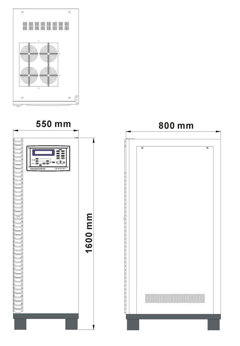
10KVA – 60KVA
OUTLINE DRAWING
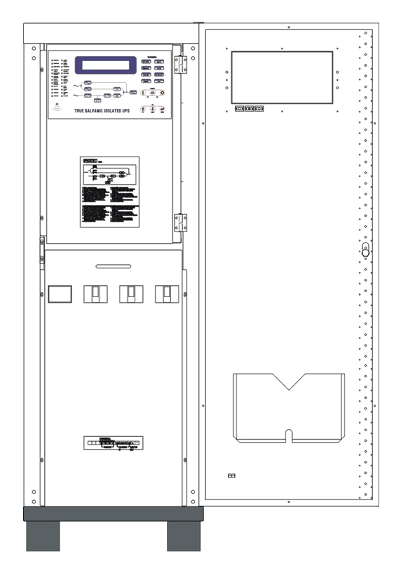
10KVA – 60KVA
INTERIOR DRAWING
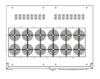
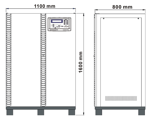
80KVA – 160KVA
OUTLINE DRAWING
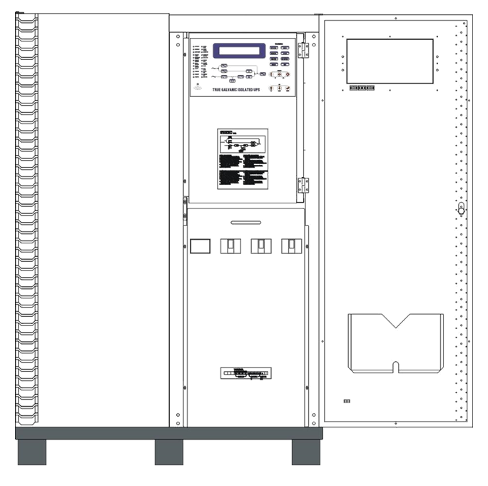
80KVA – 160KVA
INTERIOR DRAWING
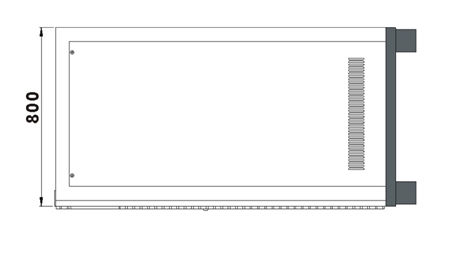
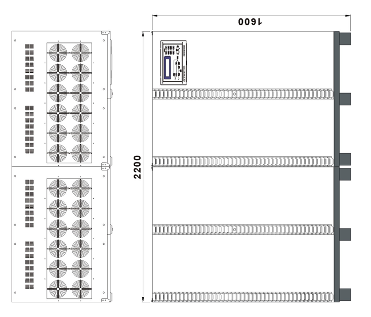
200KVA – 320KVA
OUTLINE DRAWING
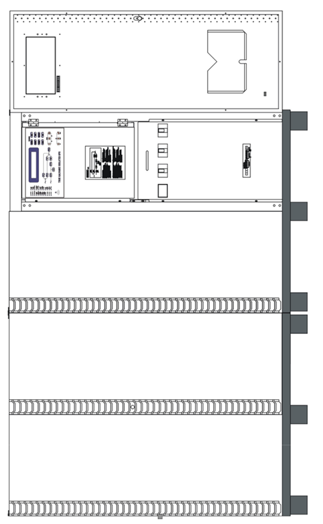
200KVA – 320KVA
INTERIOR DRAWING
INTER-PCB DIAGRAM
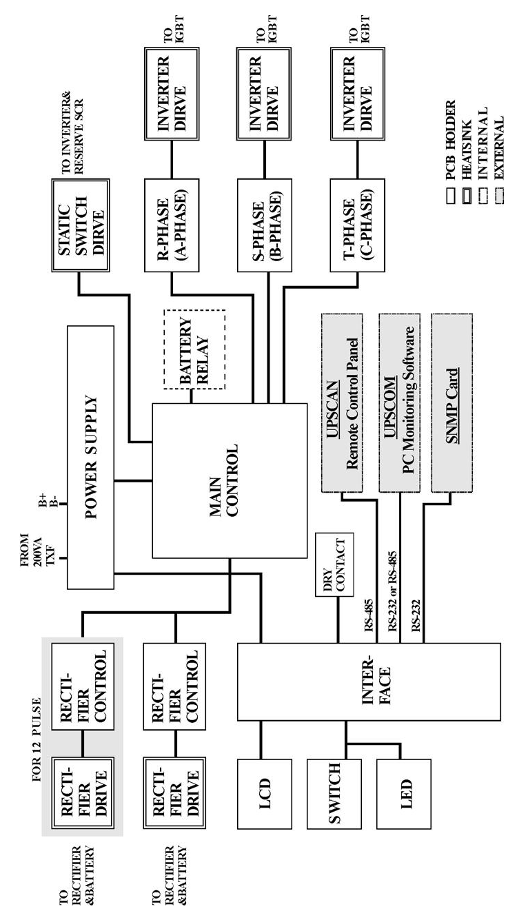
1.8. Front Panel
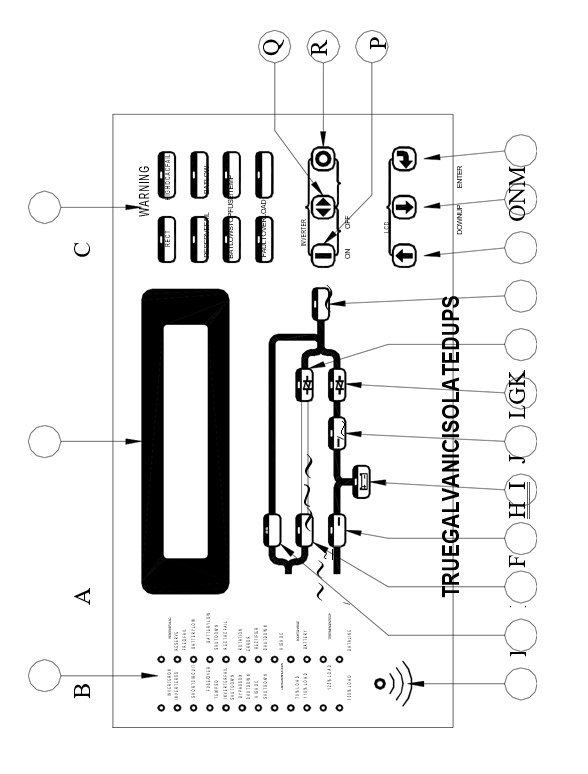
The front panel is located at the front of the PCB holder. It gathers the real time information of the UPS and shows them clearly to the user. It also provides switches for controlling and setting the UPS. Through this panel, the UPS can be not only a stand alone machine supplying the load, but also closely monitored by the user. Each part of the panel is explained below.
A. LCD display: Real time status, data or historical events are displayed on the LCD. The UPS parameters, real time clock, inverter, and buzzer also can be set through this LCD. The LCD is back-lighted by LEDs to provide a sharp display. In order to lengthen the LED’s life time, the LED are automatically shut off 3 minutes after no key is activated, but will light up again when one of the up/down/enter key is pushed.
B. Status LEDs: 24 LEDs, representing all of the important information of the UPS, provide the most up to date information to the user. Therefore these LEDs are especially important when abnormal conditions occur. The 24 information items are as shown below:
INVERTER ON – inverter is running.
INVERTER SS – inverter static switch conducts while the reserve static switch is opened.
SHORT CIRCUIT – UPS output is in short circuit state.
FUSE/OVER TEMP SD – inverter shutdown due to either fuse broken or over temperature condition.
INVERTER FAIL SHUTDOWN – inverter shutdown due to inverter output voltage too low.
BYPASS ON SHUTDOWN – inverter shutdown due to bypass breaker being closed while the inverter is running.
HIGH DC SHUTDOWN – inverter shutdown due to overly high DC bus voltage condition while the inverter is running.
OVERLOAD SHUTDOWN – inverter shutdown due to overload of the inverter for a period over that which the inverter can endure; will restart 7 seconds after overload removed.
70% LOAD – load connected to the output is at or over 70% of the UPS rating.
110% LOAD – load connected to the output is over 110% of the UPS rating.
125% LOAD – load connected to the output is over 125% of the UPS rating.
150% LOAD – load connected to the output is over 150% of the UPS rating.
RESERVE AC FAIL – reserve AC magnitude is out of range.
RESERVE FREQ FAIL – reserve frequency is out of range.
BATTERY LOW – DC bus (or battery) is lower than 320VDC, low battery shutdown is approaching.
BATTERY LOW SHUTDOWN – inverter shutdown due to DC bus (or battery) lower than 295VDC (lower than the acceptable DC voltage of the inverter).
RECT AC FAIL – rectifier AC magnitude is out of range.
ROTATION ERROR – rectifier AC phase rotation is incorrect.
RECTIFIER SHUTDOWN – rectifier shutdown due to DC bus too high (over 445VDC), will automatically restart 30 seconds after abnormal situation has been cleared.
HIGH DC – DC voltage over 430VDC and the bus voltage will be limited at this voltage.
BOOST CHARGE – the batteries are being boost charged by the rectifier.
BATTERY TEST – batteries are being tested.
EMERGENCY STOP – inverter shutdown due to emergency stop switch pushed.
DATA LINE – blinks when data is transmitted to or received from the communication port.
C. Warning LEDs: When abnormal condition happens, these LEDs will light to warn the user according to the cause of the faulty condition. Therefore all these LEDs should be extinguished under normal condition. These LEDs are as shown below:
RECT AC FAIL – rectifier AC input is abnormal either due to AC magnitude out of the range or phase rotation error, rectifier shutdown.
RESERVE FAIL – reserve AC input is abnormal either due to AC magnitude out of range or frequency out of range.
FUSE/TEMP –Inverter fuse is blown or over temperature condition exists.
OVERLOAD – output is overloaded by over 110%, 125% or 150%.
HIGH DC – the LED will light as long as the DC voltage is over 430VDC.
BAT LOW – the LED will light as long as the DC voltage is lower than 320VDC.
BAT LOW STOP – the LED will light as long as the DC voltage is lower than 295VDC, inverter cannot start.
FAULT – the inverter is shutdown due to abnormal conditions such as overload, short circuit, high DC, fuse over temperature, bypass breaker on or emergency stop.
Since these LEDs are located behind the transparent window, the user can see them clearly without opening the door.
D. Audible (buzzer) alarm: The user should not be expected to watch the UPS all the time. Therefore, when abnormal conditions occur, an audible sound should be emitted to warn the user to check the status of the UPS. The alarm buzzer will beep under any one of the following conditions:
INVERTER IS OVERLOADED-
>110%, beep once / 3 seconds
>125%, beep once / second
>150%, beep twice / second
BACK- UP
>320VDC, beep once / 3 seconds
<320VDC, beep twice / second
<295VDC, no beeping
INVERTER IS SHORT CIRCUITED – beep continuously FUSE BROKEN – beep continuously
HEAT SINK OVER TEMPERATURE – beep continuously
HIGH DC SHUTDOWN – beep continuously
BYPASS ON STOP – beep continuously
EMERGENCY STOP – (emergency power off) beep continuously
The buzzer will also beep once every time the inverter is switched on or off to acknowledge to the user that his key is valid and accepted.
E. Bypass LED: This LED will light when the maintenance bypass breaker is closed. When the maintenance bypass breaker is closed, the inverter cannot be switched on and will stop immediately even when inverter is already running.
F. Reserve LED: This LED will light when the reserve breaker is closed, and there is AC power supply present at the reserve terminal.
G. Rectifier LED: This LED will light when the rectifier is operating normally, meaning the rectifier Mains are within the range specified, the rotation sequence of three phases is correct, the rectifier breaker is closed, and no high DC voltage is on the bus.
H. Back-up LED: This LED will light when the UPS is in back-up mode. This is also as the indicator for battery test result. If the battery test does not pass, this LED will flash even if the UPS is not in back-up mode, to prompt the user to change the batteries.
I. Inverter LED: This LED will light when the inverter is switched on, indicating whether the inverter is running or not.
J. Inverter SS LED: This LED will light when the inverter static switch is turned on and the reserve static switch is turned off, i.e., the load is supplied from the inverter. Usually this LED will light 7 seconds after the inverter is switched on.
K. Reserve SS LED: This LED will light when the reserve static switch is turned on and the inverter static switch is turned off, i.e., the load is supplied from the reserve. Since the reserve static switch and inverter static switch will never both turn on simultaneously, the Inverter SS LED and the Reserve SS LED should never both be lit simultaneously.
L. Output LED: This LED will light when there is AC power present at the output terminal. This is an important indication to the user at to whether AC is available at the output or not.
M. Up key: This is a LCD control key. It is for moving the cursor one item upward when items are being selected or for changing the number/character forward when data or parameter of the UPS is being set.
N. Down key: This is a LCD control key. It is for moving the cursor one item downward when items are being selected or for changing the number/ character backward when data or parameter of the UPS is being set.
O. Enter key: This is a LCD control key. It is for changing backward to the previous page, and also for confirming the number/character /item is selected.
P. Inverter on switch: This is an inverter control switch. When this key is pushed with the control key simultaneously, the inverter will be switched on.
Q. Inverter control switch: This is an inverter control switch. When this key is pushed with the inverter on key simultaneously, the inverter will be switched on. Similarly, when this key is pushed with the inverter off key simultaneously, the inverter will be switched off. Thus, this key is a guard for mistaken key strokes.
R. Inverter off switch: This is an inverter control switch. When this key is pushed with the control key simultaneously, the inverter will be switched off.
- TECHNICAL SPECIFICATION
2.1. 10KVA ~ 60KVA UPS 3-Phase Input / 3-Phase Output
TECHNICAL SPECIFICATION
RECTIFIER
| INPUT VOLTAGE | 380 / 400 / 415VAC 3 Phase 4 Wire | |||||||||
| INPUT RANGE | 307 – 520V | |||||||||
| INPUT FREQUENCY | 50 / 60 Hz +/- 7% | |||||||||
| INPUT POWER FACTOR | 0.8 | |||||||||
| NORMAL INPUT CURRENT(A) | 18 | 36 | 54 | 72 | 90 | 108 | ||||
| MAXIMUM INPUT CURRENT(A) | 24 | 45 | 68 | 90 | 113 | 136 | ||||
| POWER WALK IN | 0% – 100% : 20 sec | |||||||||
| EFFICIENCY | 99% | |||||||||
| VOLTAGE REGULATION | 1% | |||||||||
| CURRENT LIMIT(A) | 27 | 54 | 81 | 108 | 135 | 162 | ||||
| RIPPLE VOLTAGE | 0.5% | |||||||||
| BATTERY | ||||||||||
| BATTERY TYPE | SEAL LEAD ACID / NiCd | |||||||||
| NO. OF CELLS | 174 / 271 | |||||||||
| VOLTAGE RANGE | 295 – 410VDC / 285-415VDC | |||||||||
| MAXIMUM CHARGE | 5 | 10 | 15 | 20 | 25 | 30 | ||||
| CURRENT (ADC) | ||||||||||
| BATTERY LOW VOLTAGE | 320VDC / 305VDC | |||||||||
| BATTERY LOW STOP VOLTAGE | 295VDC / 285VDC | |||||||||
| BOOST CHARGE | 402VDC / 415VDC | |||||||||
| FLOAT CHARGE | 390VDC / 410VDC | |||||||||
INVERTER
| DC INPUT RANGE | 285 – 420VDC | ||||||||||
| WAVE FORM | SINUSOID | ||||||||||
| OUTPUT VOLTAGE | 380 / 400 / 415 VAC 3 Phase 4 Wire | ||||||||||
| OUTPUT POWER FACTOR | 0.8 | ||||||||||
| VOLTAGE REGULATION 100% | +/-1% | ||||||||||
| UNBALANCE LOAD | |||||||||||
| FREQUENCY LOCK RANGE | 45 – 55 Hz / 55 – 65 Hz | ||||||||||
| OUTPUT FREQUENCY | 50 / 60 Hz + / – 0.1 Hz | ||||||||||
| (FREE RUNNING) | |||||||||||
| PHASE SHIFT UNDER | 120%+/-0.5∘ | ||||||||||
| 100% UNBALANCE LOAD | |||||||||||
| THD (LINEAR LOAD) | < 2 % | ||||||||||
| <110% | CONTINUOUS | ||||||||||
| OVERLOAD | 110 – 125% | 15 min | |||||||||
| 125 – 150% | 10 min | ||||||||||
| > 150% | 60 sec | ||||||||||
| EFFICIENCY (100% LOAD) | 93% | 93% | 93% | 93.5% | 93.5% | 94% | |||||
| MAXIMUM OUTPUT | 43 | 87 | 130 | 174 | 218 | 260 | |||||
| PEAK CURRENT(A) | |||||||||||
| STATIC SWITCH | |||||||||||
| VOLTAGE RANGE | 173 – 277 VAC (LINE TO NEUTRAL) | ||||||||||
| FREQUENCY RANGE | 45 – 55 Hz / 55 – 65 Hz | ||||||||||
| EFFICIENCY | 99.5% | ||||||||||
| TRANSFER TIME: | |||||||||||
| – MAINS -> INVERTER | 0 ms | ||||||||||
| – INVERTER -> MAINS | 0 ms | ||||||||||
| OVERLOAD | 100% | 30 sec | |||||||||
| 300% | 1 sec | ||||||||||
| ISOLATION WITH OUTPUT | YES | ||||||||||
| KVA | 10 | 20 | 30 | 40 | 50 | 60 | ||
| OVERALL CHARACTERISTICS | ||||||||
| OVERALL EFFICIENCY | 91% | 91% | 91% | 91.5% | 92% | 92% | ||
| OPERATING ENVIRONMENT: | ||||||||
| – TEMPERATURE | 0–40℃ (32–104℉ ) | |||||||
| – HUMIDITY | 0% – 90% ( NON–CONDENSING ) | |||||||
| – ALTITUDE | <1500 M ABOVE SEA LEVEL | |||||||
| MAXIMUM HEAT | 0.65 | 1.3 | 1.9 | 2.6 | 3 | 3.5 | ||
| DISSIPATION(KW) | ||||||||
| WEIGHT(Kg) (No Battery) | 300 | 400 | 470 | 520 | 560 | 630 | ||
| DIMENSION: | ||||||||
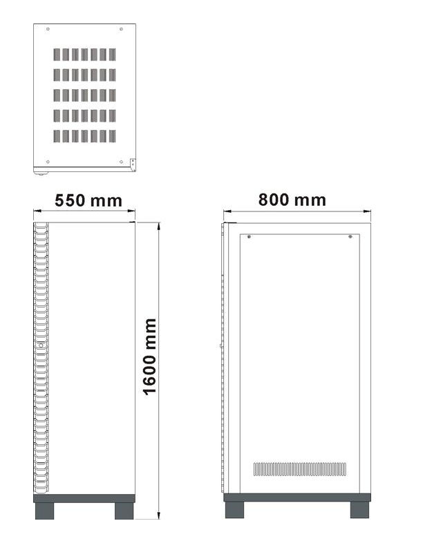
| – HEIGHT(mm) | 1600 | |||||||
| – WIDTH(mm) | 550 | |||||||
| – DEPTH(mm) | 800 | |||||||
| – AUDIBLE NOISE | < 65 dBA (AT 1 m) | |||||||
| STANDARDS: | ||||||||
| – EN50091-1,-2 | YES | |||||||
| – FCC CLASS A | YES | |||||||
| PROTECTIONS: | ||||||||
| – SHORT CIRCUIT | RECTIFIER, RESERVE, BYPASS NFB | |||||||
| – LIGHTNING | MOV | |||||||
| – EMC FILTER | INPUT & OUTPUT | |||||||
| – GALVANIC ISOLATION | BETWEEN INPUT & OUTPUT | |||||||
| DATA DISPLAY BY LCD | YES | |||||||
| INDICATIONS & ALARMS: | ||||||||
| – LED,LCD,BUZZER | YES | |||||||
| DRY CONTACT | YES | |||||||
| BATTERY START | YES | |||||||
☆All specifications mentioned above are subject to change without prior notice.
2.2. 80KVA ~ 160KVA UPS 3-Phase Input / 3-Phase Output
TECHNICAL SPECIFICATION
RECTIFIER
| INPUT VOLTAGE | 380 / 400 / 415VAC 3 Phase 4 Wire | ||||||
| INPUT RANGE | 307 – 520V | ||||||
| INPUT FREQUENCY | 50 / 60 Hz +/- 7% | ||||||
| INPUT POWER FACTOR | 0.8 | ||||||
| NORMAL INPUT CURRENT(A) | 144 | 180 | 216 | 288 | |||
| MAXIMUM INPUT CURRENT(A) | 180 | 225 | 270 | 360 | |||
| POWER WALK IN | 0% – 100% : 20 sec | ||||||
| EFFICIENCY | 99% | ||||||
| VOLTAGE REGULATION | 1% | ||||||
| CURRENT LIMIT(A) | 216 | 270 | 324 | 432 | |||
| RIPPLE VOLTAGE | 0.5% | ||||||
| BATTERY | |||||||
| BATTERY TYPE | SEAL LEAD ACID / NiCd | ||||||
| NO. OF CELLS | 174 / 271 | ||||||
| VOLTAGE RANGE | 295 – 410VDC / 285-415VDC | ||||||
| MAXIMUM CHARGE | 40 | 50 | 60 | 80 | |||
| CURRENT (ADC) | |||||||
| BATTERY LOW VOLTAGE | 320VDC / 305VDC | ||||||
| BATTERY LOW STOP VOLTAGE | 295VDC / 285VDC | ||||||
| BOOST CHARGE | 402VDC / 415VDC | ||||||
| FLOAT CHARGE | 390VDC / 410VDC | ||||||
INVERTER
| DC INPUT RANGE | 285 – 420VDC | |||||||||
| WAVE FORM | SINUSOID | |||||||||
| OUTPUT VOLTAGE | 380 / 400 / 415 VAC 3 Phase 4 Wire | |||||||||
| OUTPUT POWER FACTOR | 0.8 | |||||||||
| VOLTAGE REGULATION | +/-1% | |||||||||
| 100% UNBALANCE LOAD | ||||||||||
| FREQUENCY LOCK RANGE | 45 – 55 Hz / 55 – 65 Hz | |||||||||
| OUTPUT FREQUENCY | 50 / 60 Hz + / – 0.1 Hz | |||||||||
| (FREE RUNNING) | ||||||||||
| PHASE SHIFT UNDER | 120%+/-0.5∘ | |||||||||
| 100% UNBALANCE LOAD | ||||||||||
| THD (LINEAR LOAD) | < 2 % | |||||||||
| <110% | CONTINUOUS | |||||||||
| OVERLOAD | 110 – 125% | 15 min | ||||||||
| 125 – 150% | 10min | |||||||||
| > 150% | 60 sec | |||||||||
| EFFICIENCY (100% LOAD) | 94.5% | 94.5% | 95% | 95% | ||||||
| MAXIMUM OUTPUT | 348 | 432 | 520 | 693 | ||||||
| PEAK CURRENT(A) | ||||||||||
| STATIC SWITCH | ||||||||||
| VOLTAGE RANGE | 173 – 277 VAC (LINE TO NEUTRAL) | |||||||||
| FREQUENCY RANGE | 45 – 55 Hz / 55 – 65 Hz | |||||||||
| EFFICIENCY | 99.5% | |||||||||
| TRANSFER TIME: | ||||||||||
| – MAINS -> INVERTER | 0 ms | |||||||||
| – INVERTER -> MAINS | 0 ms | |||||||||
| OVERLOAD | 100% | 30 sec | ||||||||
| 300% | 1 sec | |||||||||
| ISOLATION WITH OUTPUT | YES | |||||||||
| KVA | 80 | 100 | 120 | 160 | |||
| OVERALL CHARACTERISTICS | |||||||
| OVERALL EFFICIENCY | 92.5% | 92.5% | 93% | 93% | |||
| OPERATING ENVIRONMENT: | |||||||
| – TEMPERATURE | 0-40℃ (32-104℉ ) | ||||||
| – HUMIDITY | 0% – 90% ( NON–CONDENSING ) | ||||||
| – ALTITUDE | <1500 M ABOVE SEA LEVEL | ||||||
| MAXIMUM HEAT | 4.6 | 5.4 | 6.5 | 8.7 | |||
| DISSIPATION(KW) | |||||||
| WEIGHT(Kg) (No Battery) | 950 | 1250 | 1400 | 1600 | |||
| DIMENSION: | |||||||
| – HEIGHT(mm) | 1600 | ||||||
| – WIDTH(mm) | 1100 | ||||||
| – DEPTH(mm) | 800 | ||||||
| – AUDIBLE NOISE | < 65 dBA (AT 1 m) | ||||||
| STANDARDS: | |||||||
| – EN50091-1,-2 | YES | ||||||
| – FCC CLASS A | YES | ||||||
| PROTECTIONS: | |||||||
| – SHORT CIRCUIT | RECTIFIER, RESERVE, BYPASS NFB | ||||||
| – LIGHTNING | MOV | ||||||
| – EMC FILTER | INPUT & OUTPUT | ||||||
| – GALVANIC ISOLATION | BETWEEN INPUT & OUTPUT | ||||||
| DATA DISPLAY BY LCD | YES | ||||||
| INDICATIONS & ALARMS: | |||||||
| – LED,LCD,BUZZER | YES | ||||||
| DRY CONTACT | YES | ||||||
| BATTERY START | YES | ||||||
☆All specifications mentioned above are subject to change without prior notice.
2.3. 200KVA ~ 320KVA UPS 3-Phase Input / 3-Phase Output
TECHNICAL SPECIFICATION
RECTIFIER
| INPUT VOLTAGE | 380 / 400 / 415VAC 3 Phase 4 Wire | ||||||
| INPUT RANGE | 307 – 520V | ||||||
| INPUT FREQUENCY | 50 / 60 Hz +/- 7% | ||||||
| INPUT POWER FACTOR | 0.8 | ||||||
| NORMAL INPUT CURRENT(A) | 350 | 420 | 525 | 560 | |||
| MAXIMUM INPUT CURRENT(A) | 437 | 525 | 656 | 700 | |||
| POWER WALK IN | 15% – 100% : 15 sec | ||||||
| EFFICIENCY | 99% | ||||||
| VOLTAGE REGULATION | 1% | ||||||
| CURRENT LIMIT(A) | 525 | 630 | 788 | 840 | |||
| RIPPLE VOLTAGE | 0.5% | ||||||
| BATTERY | |||||||
| BATTERY TYPE | SEAL LEAD ACID / NiCd | ||||||
| NO. OF CELLS | 174 / 271 | ||||||
| VOLTAGE RANGE | 295 – 410VDC / 285-415VDC | ||||||
| MAXIMUM CHARGE | 100 | 120 | 150 | 160 | |||
| CURRENT (ADC) | |||||||
| BATTERY LOW VOLTAGE | 320VDC / 305VDC | ||||||
| BATTERY LOW STOP VOLTAGE | 295VDC / 285VDC | ||||||
| BOOST CHARGE | 402VDC / 415VDC | ||||||
| FLOAT CHARGE | 390VDC / 410VDC | ||||||
INVERTER
| DC INPUT RANGE | 285 – 420VDC | |||||||||
| WAVE FORM | SINUSOID | |||||||||
| OUTPUT VOLTAGE | 380 / 400 / 415 V 3 Phase 4 Wire | |||||||||
| OUTPUT POWER FACTOR | 0.8 | |||||||||
| VOLTAGE REGULATION | +/-1% | |||||||||
| 0-100% LOAD | ||||||||||
| FREQUENCY LOCK RANGE | 45 – 55 Hz / 55 – 65 Hz | |||||||||
| OUTPUT FREQUENCY | 50 / 60 Hz + / – 0.1 Hz | |||||||||
| (FREE RUNNING) | ||||||||||
| PHASE DIFFERENCE WITH | 120°+ / – 0.5° | |||||||||
| RESERVE INPUT | ||||||||||
| THD (LINEAR LOAD) | < 5 % | |||||||||
| <110% | CONTINUOUS | |||||||||
| OVERLOAD | 110 – 125% | 15 min | ||||||||
| 125 – 150% | 10 min | |||||||||
| > 150% | 60 sec | |||||||||
| EFFICIENCY(100% LOAD) | 95% | 95% | 95% | 95% | ||||||
| MAXIMUM OUTPUT | 800 | 1000 | 1250 | 1300 | ||||||
| PEAK CURRENT(A) | ||||||||||
| STATIC SWITCH | ||||||||||
| VOLTAGE RANGE | 173 – 277 VAC (LINE TO NEUTRAL) | |||||||||
| FREQUENCY RANGE | 45 – 55 Hz / 55 – 65 Hz | |||||||||
| EFFICIENCY | 99.5% | |||||||||
| TRANSFER TIME: | ||||||||||
| – MAINS -> INVERTER | 0 ms | |||||||||
| – INVERTER -> MAINS | 0 ms | |||||||||
| OVERLOAD | 100% | 30 sec | ||||||||
| 300% | 1 sec | |||||||||
| ISOLATION WITH OUTPUT | YES | |||||||||
OVERALL CHARACTERISTICS
| OVERALL EFFICIENCY | 93% | 93% | 93% | 93% | ||
| OPERATING ENVIRONMENT: | ||||||
| – TEMPERATURE | 0-40℃ (32-104℉ ) | |||||
| – HUMIDITY | 0% – 90% ( NON–CONDENSING ) | |||||
| – ALTITUDE | <1500 M ABOVE SEA LEVEL | |||||
| MAXIMUM HEAT | 11.5 | 13 | 16.3 | 17.4 | ||
| DISSIPATION(KW) | ||||||
| WEIGHT(Kg) (No Battery) | 2500 | 2700 | 2900 | 3000 | ||
| DIMENSION: | ||||||
| – HEIGHT(mm) | 1600 | |||||
| – WIDTH(mm) | 2200 | |||||
| – DEPTH(mm) | 800 | |||||
| – AUDIBLE NOISE | < 67 dBA (AT 1 m) | |||||
| STANDARDS: | ||||||
| -EN50091-1,2 | YES | |||||
| -FCC CLASS A | YES | |||||
| PROTECTIONS: | ||||||
| – SHORT CIRCUIT | RECTIFIER, RESERVE, BYPASS NFB | |||||
| – LIGHTNING | MOV | |||||
| – EMC FILTER | INPUT & OUTPUT | |||||
| – GALVANIC ISOLATION | BETWEEN INPUT & OUTPUT | |||||
| DATA DISPLAY BY LCD | YES | |||||
| INDICATIONS & ALARMS: | ||||||
| – LED,LCD,BUZZER | YES | |||||
| DRY CONTACT | YES | |||||
| BATTERY START | YES | |||||
☆All specifications mentioned above are subject to change without prior notice.
2.4. 10KVA ~ 50KVA UPS 3–Phase Input / 1-Phase Output
TECHNICAL SPECIFICATION
RECTIFIER
| INPUT VOLTAGE | 380 / 400 / 415VAC 3 Phase 4 Wire | ||||||||
| INPUT RANGE | 307 – 520V | ||||||||
| INPUT FREQUENCY | 50 / 60 Hz +/- 7% | ||||||||
| INPUT POWER FACTOR | 0.8 | ||||||||
| NORMAL INPUT CURRENT(A) | 18 | 36 | 54 | 72 | 90 | ||||
| MAXIMUM INPUT CURRENT(A) | 24 | 45 | 68 | 90 | 113 | ||||
| POWER WALK IN | 0% – 100% : 20 sec | ||||||||
| EFFICIENCY | 99% | ||||||||
| VOLTAGE REGULATION | 1% | ||||||||
| CURRENT LIMIT(A) | 27 | 54 | 81 | 108 | 135 | ||||
| RIPPLE VOLTAGE | 0.5% | ||||||||
| BATTERY | |||||||||
| BATTERY TYPE | SEAL LEAD ACID / NiCd | ||||||||
| NO. OF CELLS | 174 / 271 | ||||||||
| VOLTAGE RANGE | 295 – 410VDC / 285-415VDC | ||||||||
| MAXIMUM CHARGE | 5 | 10 | 15 | 20 | 25 | ||||
| CURRENT (ADC) | |||||||||
| BATTERY LOW VOLTAGE | 320VDC / 305VDC | ||||||||
| BATTERY LOW STOP VOLTAGE | 295VDC / 285VDC | ||||||||
| BOOST CHARGE | 402VDC / 415VDC | ||||||||
| FLOAT CHARGE | 390VDC / 410VDC | ||||||||
INVERTER
| DC INPUT RANGE | 285 – 420VDC | ||||||||||
| WAVE FORM | SINUSOID | ||||||||||
| OUTPUT VOLTAGE | 220 / 230 / 240 VAC, 1p2w or 1p3w | ||||||||||
| OUTPUT POWER FACTOR | 0.8 | ||||||||||
| VOLTAGE REGULATION | +/-1% | ||||||||||
| 0-100% LOAD | |||||||||||
| FREQUENCY LOCK RANGE | 45 – 55 Hz / 55 – 65 Hz | ||||||||||
| OUTPUT FREQUENCY | 50 / 60 Hz + / – 0.1 Hz | ||||||||||
| (FREE RUNNING) | |||||||||||
| PHASE DIFFERENCE WITH | +/-0.5∘ | ||||||||||
| RESERVE INPUT | |||||||||||
| THD (LINEAR LOAD) | < 2 % | ||||||||||
| <110% | CONTINUOUS | ||||||||||
| OVERLOAD | 110 – 125% | 15 min | |||||||||
| 125 – 150% | 10 min | ||||||||||
| > 150% | 60 sec | ||||||||||
| EFFICIENCY (100% LOAD) | 93% | 93% | 93% | 93.5% | 93.5% | ||||||
| MAXIMUM OUTPUT | 130 | 260 | 390 | 520 | 650 | ||||||
| PEAK CURRENT(A) | |||||||||||
| STATIC SWITCH | |||||||||||
| VOLTAGE RANGE | 173 – 277 VAC (LINE TO | ||||||||||
| FREQUENCY RANGE | 45 – 55 Hz / 55 – 65 Hz | ||||||||||
| EFFICIENCY | 99.5% | ||||||||||
| TRANSFER TIME: | |||||||||||
| – MAINS -> INVERTER | 0 ms | ||||||||||
| – INVERTER -> MAINS | 0 ms | ||||||||||
| OVERLOAD | 100% | 30 sec | |||||||||
| 300% | 1 sec | ||||||||||
| ISOLATION WITH OUTPUT | YES | ||||||||||
| KVA | 10 | 20 | 30 | 40 | 50 | |
| OVERALL CHARACTERISTICS | ||||||
| OVERALL EFFICIENCY | 91% | 91% | 91% | 91.5% | 92% | |
| OPERATING ENVIRONMENT: | ||||||
| – TEMPERATURE | 0-40℃ (32-104℉ ) | |||||
| – HUMIDITY | 0% – 90% ( NON–CONDENSING ) | |||||
| – ALTITUDE | <1500 M ABOVE SEA LEVEL | |||||
| MAXIMUM HEAT | 0.65 | 1.3 | 1.9 | 2.6 | 3 | |
| DISSIPATION(KW) | ||||||
| WEIGHT(Kg) (No Battery) | 300 | 400 | 470 | 520 | 560 | |
| DIMENSION: | ||||||
| – HEIGHT(mm) | 1600 | |||||
| – WIDTH(mm) | 550 | |||||
| – DEPTH(mm) | 800 | |||||
| – AUDIBLE NOISE | < 65 dBA (AT 1 m) | |||||
| STANDARDS: | ||||||
| – EN50091-1,-2 | YES | |||||
| – FCC CLASS A | YES | |||||
| PROTECTIONS: | ||||||
| – SHORT CIRCUIT | RECTIFIER, RESERVE, BYPASS NFB | |||||
| – LIGHTNING | MOV | |||||
| – EMC FILTER | INPUT & OUTPUT | |||||
| – GALVANIC ISOLATION | BETWEEN INPUT & OUTPUT | |||||
| DATA DISPLAY BY LCD | YES | |||||
| INDICATIONS & ALARMS: | ||||||
| – LED,LCD,BUZZER | YES | |||||
| DRY CONTACT | YES | |||||
| BATTERY START | YES | |||||
☆All specifications mentioned above are subject to change without prior notice.
- INSTALLATION
3.1. Site & Environment Considerations
The main function of the UPS is to provide a safe, clean independent electrical supply to the load so that it is free from any random variations, disturbances or interruptions of the utility Mains. The UPS also provides a constant power supply which is perfectly regulated in both voltage and frequency. And when the Mains are not available, the UPS can provide optimal back-up time depending on the battery bank capacity connected to it.
Usually the life expectancy of the UPS is 5 to 10 years (batteries are not included, because life expectancy of batteries depend on the type of battery, the temperature and humidity of the environment in which it is installed, and the type of charger that is applied to the battery). Therefore optimal life expectancy of the UPS can be achieved by careful consideration of the site and environment.
The following precautions and recommendations should be checked in considering the site and environment of the UPS:
- The UPS should be located in a place with adequate ventilation (refer to the specification of the heat dissipation of the UPS). If the UPS is installed indoors, care must be taken in insuring the evacuation of heat from a closed room.
- Adequate space (at least 1M) should be allowed to open the door, unobstructed by other objects, for operation or maintenance. Adequate space (at least 1M) should be allowed at the top of the UPS, because heat dissipation is ventilated through the top openings.
- Do not put any objects on the top of the UPS that may obstruct ventilation. Do not locate the UPS near any heat source, machinery which produce metallic dust or powder, or any facility that will produce corrosive substances or vapor.
- Protect the UPS from accidental damage from fire extinguishing (sprinkler) systems. Protect the UPS from abnormal conditions with a dedicated cutoff from the incoming power.
- It is necessary to guarantee the temperature and humidity values of the site into which the UPS will be installed. These should be within the range allowed by the specification. The UPS is capable of continuous normal operation within a temperature range of 0℃(32℉) to 40℃(104℉). For optimal performance and reliability, and to prolong UPS’s lifetime, it is recommended to keep the environment temperature below 25℃, and humidity below 80%.
- If the UPS is installed outdoors, avoid direct exposure of the UPS to the sunlight, wind, and rain. Avoid any exposure to sand or dust.
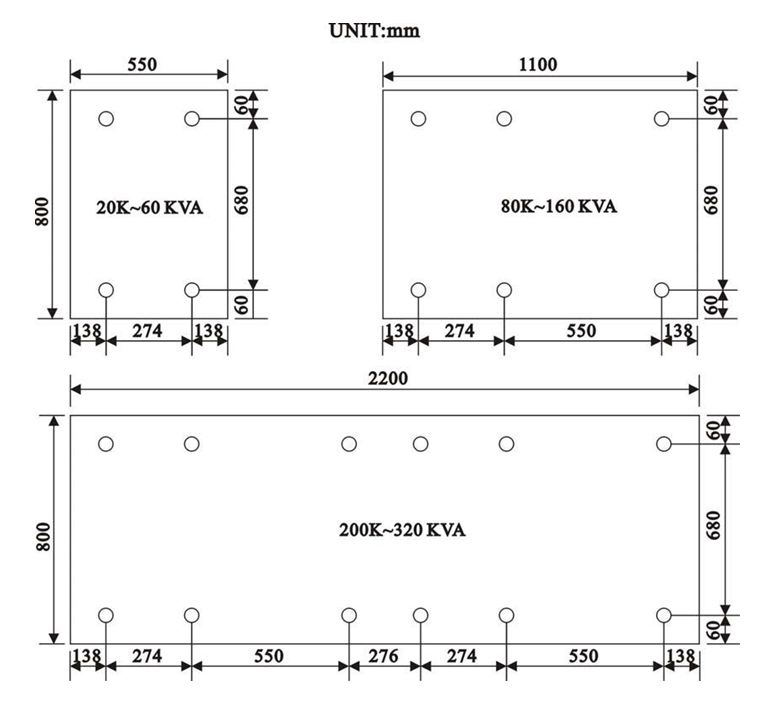
- The floor loading capacity should be high enough to endure the weight of the UPS. The UPS is mounted on four right-angled steel angles. Insert corresponding bolts and nut2 (dia.1/2”) into the floor for securing the UPS on the floor when it is located in an area where earthquakes is possible, or where motion may occur, e.g. vehicle mounted. Layout dimensions, in millimeters, are shown below.
- Walls, ceilings, and floors near the UPS should be preferably constructed of non-combustible materials. A portable fire extinguisher should be accessible nearby in case of hazard.
- Avoid accumulating combustible materials of any sort in or around the UPS system. The floor area surrounding the UPS should be kept clean so that foreign materials are not sucked into the unit, thus causing a short circuit and damage to the system.
- Access to the UPS room should be limited to a minimum number of operation and maintenance personnel only. The doors should be kept locked and the keys should be confined to authorized personnel only.
- Personnel who operate or maintain the UPS system should be proficient in normal and emergency operational procedures. New personnel should be trained and qualified prior to operating the equipment.
- Although the UPS has passed International EMC tests, it is recommended that the UPS not be installed near any equipment that is susceptible to electro-magnetic interference, such as computer systems, monitors, radios, etc.
- It is preferable to place the UPS near to the source rather than near to the load.
3.2. Unpacking
Carefully unpack the UPS, and then carefully locate the UPS onto the site which has selected, with all the points in section 3.1 kept in mind.
The UPS has had detailed production and QC testing of all the electrical and mechanical characteristics prior to shipment from the factory. Therefore, the UPS should be in proper condition upon receipt. Once received, the UPS should be first checked visually to determine if any physical damage has occurred during transportation.
Then check to insure that all the accessories/options (match with your purchase order) have been included.
- DOOR KEY
- THIS INSTRUCTION MANUAL
- BATTERY FUSE (FOR BATTERY CABINET ONLY)
- SPARE SCREWS FOR COVER PLATE
- SPARE SCREWS FOR CONNECTION TERMINALS etc.
Lastly, check to insure that the specification of the UPS is identical to the specification of your order. The key items in the specification you must check are:
- RATED POWER OF THE UPS,
- INPUT VOLTAGE & FREQUENCY
- OUTPUT VOLTAGE & FREQUENCY
- OF OUTPUT PHASES (1Φ OR 3Φ)
- BATTERY VOLTAGE OR CELL NO.
3.3. Cable Selection
The following tables list typical information concerning the KVA of the UPS versus the size and rating of the cables. Inadequate cable size or over sized breakers will incur risk of fire or damage of insulation. Therefore, please use the following tables to determine the input circuit breaker rating and the size of cable for input, output and battery connections. These data are for reference; final decisions should be made in accordance with the local electrical codes.
| BREAKER RATING FOR INPUT | |||||||
| KVA | INPUT | Imax(A) | NFB(A) | ||||
| 10 | 230/400V 3Φ | 24 | 30 | ||||
| 20 | 230/400V 3Φ | 50 | 50 | ||||
| 30 | 230/400V 3Φ | 73 | 75 | ||||
| 40 | 230/400V 3Φ | 98 | 100 | ||||
| 50 | 230/400V 3Φ | 122 | 125 | ||||
| 60 | 230/400V 3Φ | 147 | 150 | ||||
| 80 | 230/400V 3Φ | 172 | 175 | ||||
| 100 | 230/400V 3Φ | 215 | 225 | ||||
| 120 | 230/400V 3Φ | 258 | 300 | ||||
| 160 | 230/400V 3Φ | 344 | 350 | ||||
| 240 | 230/400V 3Φ | 500 | 500 | ||||
| 320 | 230/400V 3Φ | 700 | 700 | ||||
| CABLE SIZE FOR INPUT | |||||||
| KVA | INPUT | In(A) | R/S/T(mm2) | N(mm2) | |||
| 10 | 230/400V 3Φ | 18 | 6 | 8 | |||
| 20 | 230/400V 3Φ | 36 | 8 | 14 | |||
| 30 | 230/400V 3Φ | 54 | 14 | 22 | |||
| 40 | 230/400V 3Φ | 72 | 22 | 30 |
| 50 | 230/400V 3Φ | 90 | 30 | 38 |
| 60 | 230/400V 3Φ | 108 | 38 | 50 |
| 80 | 230/400V 3Φ | 144 | 50 | 80 |
| 100 | 230/400V 3Φ | 180 | 80 | 100 |
| 120 | 230/400V 3Φ | 216 | 100 | 125 |
| 160 | 230/400V 3Φ | 288 | 60*2 | 80*2 |
| 240 | 230/400V 3Φ | 416 | 100*2 | 125*2 |
| 320 | 230/400V 3Φ | 554 | 150*2 | 200*2 |
CABLE SIZE FOR OUTPUT
| KVA | OUTPUT | In(A) | R/S/T(mm2) | N(mm2) |
| 10 | 230/400V 3Φ | 15 | 6 | 8 |
| 20 | 230/400V 3Φ | 29 | 8 | 14 |
| 30 | 230/400V 3Φ | 46 | 14 | 22 |
| 40 | 230/400V 3Φ | 58 | 22 | 30 |
| 50 | 230/400V 3Φ | 72 | 30 | 38 |
| 60 | 230/400V 3Φ | 91 | 38 | 60 |
| 80 | 230/400V 3Φ | 116 | 60 | 80 |
| 100 | 230/400V 3Φ | 144 | 80 | 100 |
| 120 | 230/400V 3Φ | 182 | 100 | 125 |
| 160 | 230/400V 3Φ | 232 | 60*2 | 80*2 |
| 240 | 230/400V 3Φ | 348 | 100*2 | 125*2 |
| 320 | 230/400V 3Φ | 463 | 125*2 | 150*2 |
| 10 | 230V 1Φ | 45 | 14 | 22 |
| 20 | 230V 1Φ | 91 | 38 | 60 |
| 30 | 230V 1Φ | 130 | 60 | 80 |
| 40 | 230V 1Φ | 182 | 100 | 125 |
| 50 | 230V 1Φ | 217 | 150 | 60*2 |
FUSE RATING & CABLE SIZE FOR BATTERY
- THE BATTERY VOLTAGE IS 295 – 410V
| KVA | Imax(A) | FUSE(A) | CABLE(mm2) |
| 10 | 30 | 35 | 14 |
| 20 | 60 | 63 | 22 |
| 30 | 90 | 100 | 38 |
| 40 | 120 | 125 | 38 |
| 50 | 150 | 160 | 50 |
| 60 | 180 | 200 | 80 |
| 80 | 240 | 125*2 | 38*2 |
| 100 | 300 | 160*2 | 50*2 |
| 120 | 360 | 200*2 | 80*2 |
| 160 | 480 | 200*2 | 80*2 |
| 240 | 720 | 200*4 | 80*4 |
| 320 | 960 | 200*4 | 80*4 |
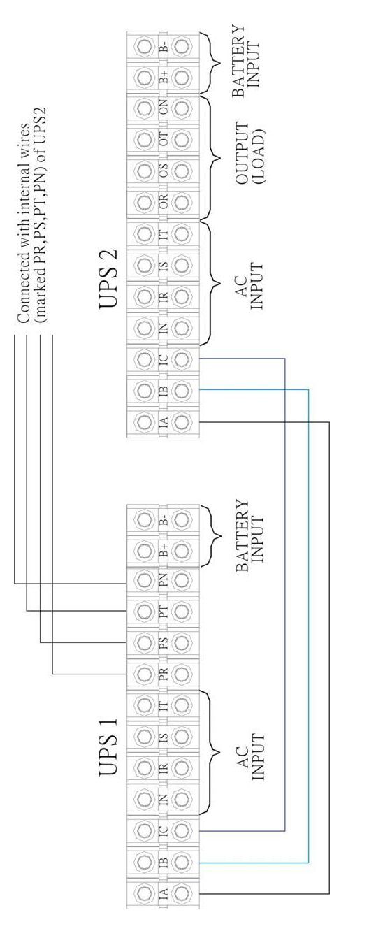
3.4. Terminal Connection
Although different sizes of UPS may have slightly different cable connection terminal blocks, all UPS connection terminal alignments falls into one of the following types:
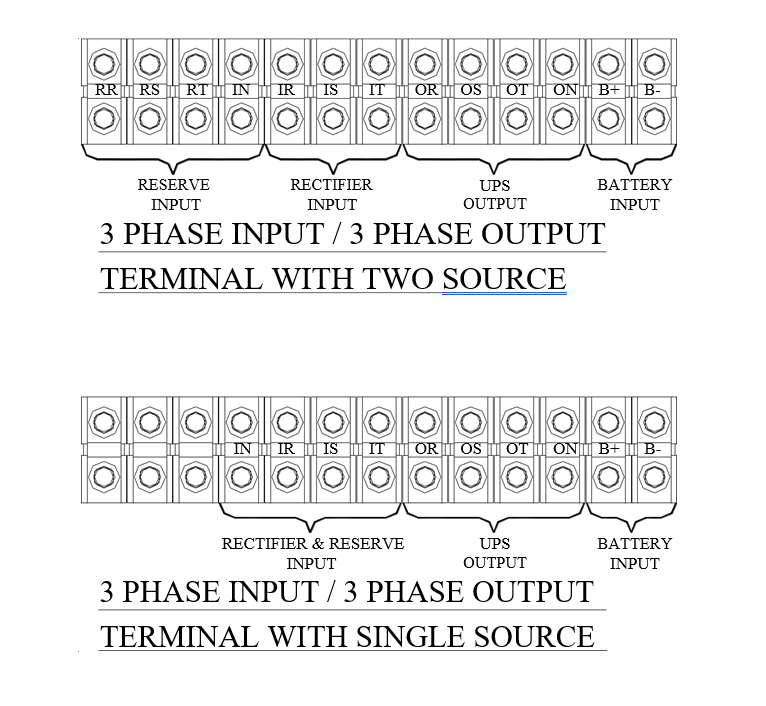
Three extra terminals are installed for convenience of changing the unit to separate reserve input.
For single phase output UPS, the current is very much larger in single phase terminal, therefore the terminal looks bigger than it is needed.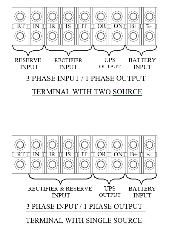
☆ ☆☆ Extra empty terminals are installed for convenience of changing the unit to separate reserve input.
- OPERATIONS
After all cables have been connected, and power source is available at the input terminals, the UPS is ready to operate. Before turning on any switch or breaker, once again check the following:
- Check that the input voltage conforms to the UPS’s rated input voltage.
- Check that the input frequency conforms with the UPS’s rated input frequency.
- Check that the load at the output is switched off.
- Check that all breakers and the battery disconnects are opened.
- Check that no foreign material is inside the UPS.
4.1. Startup Procedure
To start the UPS from complete shutoff to normal operation, follow the steps below to turn on the UPS.
- In case there is an extra input breaker for some special specification, please close the input breaker first.)
- Close the reserve breaker – The reserve and output LED on the mimic panel will light up, indicating the reserve static switch loop is energized. Therefore the output has power now. The supply of power in the UPS is established and the fans will operate.
- Close the rectifier breaker – The rectifier will be automatically started if the power source connected is correct. Wait 30 sec for DC bus voltage to rise until the warning LEDs of “BAT LOW” and “BAT LOW STOP” go off (on the front panel). Now, the DC is already ready for the inverter.
- Close the (optional) battery breaker – For safety purposes, a breaker (or fuse) is employed between the batteries and the DC bus. Now the batteries will take over to supply the DC bus if rectifier mains fail.
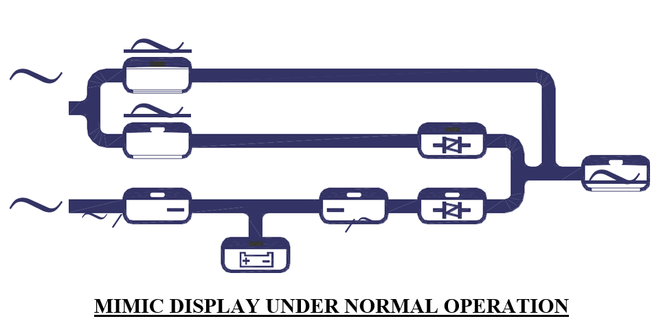
- Push inverter ON switch – To turn on the inverter, the inverter ON switch ( ) and the control switch () must be pressed simultaneously. The inverter will start working and inverter output will be established in 4 seconds. The load will automatically be transferred to the inverter 3 seconds later. Now the UPS is in normal operation.
- Check if the mimic LED is correct, as shown in the figure, above. All warning LEDs on the right side are off, two LEDs: ‘INVERTER ON’ and ‘INVERTER SS’ on the left side should be lit. If the load is over 70%, the ‘70% LOAD’ LED will also be lit.
4.2. Shutdown Procedure
If you want to shutdown the UPS completely (no power at output or inside), please follow the steps below.
- Switch off the inverter – The inverter can be switched off by pressing the inverter OFF switch ( ) and the control switch ( ) simultaneously. The load will be automatically transferred to reserve without interruption.
- Open the (optional) battery breaker – If you want to shutdown all the power of the UPS, continue to open the battery breaker. Now the DC bus is only supported by the rectifier.
- Open the rectifier breaker – Opening the rectifier breaker will further take the power source away from the DC bus, and the DC bus will start to drop slowly. After 5 minutes, the DC bus will drop to a safe level (< 20VDC).
- Open the reserve breaker – Before opening the reserve breaker, power exists at the output. After opening the reserve breaker, the output (or load) will no longer have power. Therefore, before opening the reserve breaker, insure there is no critical load connected to the output.
- If there is input breaker, open it accordingly.
- At this point, all power has been cut off, and there should none of the
LED’s or LCD’s lit. The UPS now is completely shut off.
4.3. From Inverter to Maintenance Bypass Procedure
If you want to stop the UPS for maintenance and do not stop the power supply from the load, you can follow the steps below to turn the UPS to maintenance bypass mode without interrupting the output power supply.
- Switch off the inverter – The inverter can be switched off by pressing the inverter OFF switch ( ) and the control switch ( ) simultaneously. The load will be automatically transferred to reserve without interruption.
- Open the (optional) battery breaker – You have to shutdown the power inside the UPS. Therefore, continue to open the battery breaker.
- Open the rectifier breaker – Opening the rectifier breaker will take the power source away from the DC bus, causing the DC bus to drop slowly. After 5 min., the DC bus will drop to a safe level (<20VDC).
- Close the bypass breaker – The reserve breaker and reserve static switch are still conducting. Therefore, when the maintenance bypass breaker is closed, power will flow through the bypass loop instead of the reserve loop because of the lower impedance of bypass loop.
- Open the reserve breaker – You can now open the reserve breaker to free the UPS from any power supply.
4.4. From Maintenance Bypass to Inverter Procedure
If the UPS is in maintenance bypass mode, and you want to turn the UPS to normal mode without interrupting the output AC, please follow the steps below.
- Close the reserve breaker – The reserve and output LED on the mimic will light, indicating the reserve static switch loop is energized, and the output has power. The power supply in the UPS is also established, and the fans will operate.
- Open the bypass breaker – The inverter cannot be switched on while the maintenance bypass breaker is closed (because the CPU will sense the breaker and prevent the inverter from connecting directly to AC source). Since the reserve breaker is already closed, power goes through the reserve loop if the bypass breaker is open. Thus, AC at the output will not be interrupted.
- Close the rectifier breaker – The rectifier will be automatically started if the power source connected is correct. Wait 30 sec for DC bus voltage to rise until the warning LEDs of “BAT LOW” and “BAT LOW STOP” go off (on the front panel). Now, the DC is already ready for the inverter.
- Close the (optional) battery breaker – For safety purposes, a fuse is employed in the battery to the DC bus. Now the battery will take-over to supply the DC bus if the rectifier mains fail.
- Push inverter ON switch – To turn on the inverter, the inverter ON switch ( ) and the control switch () must be pressed simultaneously. The inverter will start working and inverter output will be established in 4 seconds. The load will automatically be transferred to the inverter 3 seconds later. Now the UPS is in normal operation.
5. LCD DISPLAY
The LCD can display much more information than can the LEDs. In order to make the display sharp and readable, the LCD is back-lighted by LEDs. But to further prolong the life of the LEDs, the CPU will cut off power to the LEDs 3 minutes after the last keystroke of UP, DOWN or ENTER is pressed. The backlighting will resume if the UP, DOWN or ENTER key is subsequently pressed. Page displays of the LCD are described below. This screen will refresh once the system power is enabled (i.e. the default screen).
5.1. Menu 0 – Main Menu
| WELCOME TO USE THE UPS | ||||||||||||||
| P/N:50 | 3 | 3 | A | S/N:1 | 2 3 4 | 5 6 | 7 | 8 | 9 | 0 | ID:0 | 1 | ||
| 50KVA I: | 2 | 20/38 | 0 | V / 5 | 0 H Z | O : | 2 | 2 | 0/3 8 0V/5 | 0 H Z | ||||
| 2 0 | 0 2/0 2/0 | 1 | T U E | 0 | 8 | : | 0 0 | A M | ||||||
The first row will display the greeting text set by the factory. Changing the text of this row is not recommended. The parameter no. (P/N), serial number (S/N), and the identification number (ID) are displayed in the second row. While the third row will display the KVA rating, input rating and output rating of the UPS. Changing the parameter number of the second row will also change the rating displayed in the second row (rating is automatically generated by CPU inside the UPS according to the P/N number).
WARNING: Never change the parameter number yourself, because some parameters will be changed accordingly.
Serial number is set by factory for the convenience of maintenance personnel who may need to refer to the serial number of the UPS serviced. The identification number is set only when an external control module is connected to more than one UPS. Each UPS must have a unique number to identify itself, and it should be set by installation technical personnel after installation. The YEAR/MONTH/DATE, DAY OF THE WEEK, HOUR: MINUTE and AM (PM), from the real time clock inside the UPS, are displayed in the fourth row for user’s reference and date/time stamping in the historical data when abnormal conditions occur. Pressing one of the UP, DOWN or ENTER keys will change the LCD to the MENU 1 screen.
5.2. Menu 1 – Select Menu
| <SELECT | MENU > |
| →STATUS/WARN/FAULT | PARAMETER SET |
| REAL TIME DATA | |
| HISTORICAL DATA | EXIT |
The Select Menu is for the user to select, via the cursor (→), the type of data the user wants to view, such as, inverter on/off, buzzer on/off, charging time and magnitude, date/time etc. The cursor (→) can be moved upward by the UP(↑) key, and can be moved downward by the DOWN( ↓ ) key. The selection is confirmed by pressing the ENTER key (←┘), and change to the menu at which the cursor is pointing. If the item “PARAMETER SET” is selected, the LCD will jump into a screen which will ask the user to key in the password. See the figure below.
PASSWORD: 1234
The password is a 4 digit number which can be changed upward or downward by the UP(↑) or the DOWN(↓) key, and can be confirmed by the ENTER(←┘) key. The selection will continue if the correct password is entered, or will go back to MENU 0, the MAIN MENU, if no correct password is entered after 3 trials. The password for entering the < PARAMETER SET > menu is 1-2-3-4. The entering of MENU 12, the OTHER SETTING menu, is permitted by another password, to be used by maintenance personnel. Users can obtain this password from the manufacturer for user’s maintenance technicians.
If “EXIT” is selected (blinking instead of pointed by cursor), the screen will return to MENU 0.
5.3. Menu 2 – Status / Warning Menu

This menu is displayed when STATUS/WARN/FAULT is selected from MENU 1. The left hand side of this menu shows the real time status of the rectifier, inverter and static switch. The right hand side shows the warning or fault conditions, if any. Therefore, under normal conditions, the LCD display should be exactly as shown above. When minor abnormal conditions occur, these will be shown under the title < WARNING >. These will be overridden by a fault message if more serious abnormal conditions occur, and the title < WARNING > will change to < FAULT >. For example, if short circuit occurs at the output, this screen will display the following:

The inverter should be shut off under a short circuit condition. Since the CPU will detect a short circuit, and in order to avoid unnecessary tripping and damage to the breaker, the static switch remains connected to the inverter (will not transfer to reserve).
Listed below are all the warning conditions that can be displayed (arranged in order of priority, starting with the highest priority):
1st row : BYPASS ON / RECT AC FAIL / RECTIFIER PHASE ERROR /
RESERVE FREQ. ERROR
2nd row : 170% OVERLOAD / 150% OVERLOAD / 125% OVERLOAD / 110% OVERLOAD
3rd row : BATTERY LOW STOP / BATTERY LOW / BATTERY BAD /
BATTERY GND FAULT / BATTERY TESTING
Lists below are all the fault conditions that can be displayed:
1st row : HIGH DC SHUTDOWN
2nd row: SHORT CIRCUIT! / FUSE/OVERHEAT / OVERLOAD SHUTDOWN / EMERGENCY STOP / INVERTER ABNORMAL
3rd row : BYPASS ON SHUTDOWN
The UP (↑) or DOWN (↓) key has no function in this menu. The screen will go back to MENU 1 – the SELECT menu, when ENTER (←┘) is pressed.
5.4. Menu 3 – Real Time Data Menu
| <REAL | TIME DATA > | |
| →RECTIF | IER DATA | OTHER DATA |
| RESERVE DATA | ||
| OUTPUT | DATA | EXIT |
This menu is displayed when the REAL TIME DATA is selected from MENU 1. The cursor (→) is used to select the type of real time data the user wants to view, such as, RECTIFIER DATA, RESERVE DATA, OUTPUT DATA, OTHER DATA etc. The cursor (→) can be moved upward by the UP (↑) key, and can be moved downward by the DOWN (↓) key. The selection is confirmed by pressing the ENTER (←┘), changing the menu to that at which the cursor is pointing.
If “EXIT” is selected (blinking instead of pointed by cursor), the screen will go back to the MENU 1- the SELECT MENU.
5.5. Menu 4 – Historical Event Menu
| <DATE/TIME/EVENTS > | RUN:21YR03MO | ||||||||||||||||||
| 2 | 0 | 0 | 0 | 0 | 3 | 2 | 9 | 0 | 9 | : 3 | 2 | SHORT | C I | RCU I | T ! | ||||
| 2 | 0 | 0 | 0 | 1 | 2 | 0 | 1 | 2 | 2 | : | 1 | 5 | SHORT | C | I | RCU I | T ! | ||
| 2001 | 0 1 | 1 0 | 1 5 | : | 4 7 | HIGH DC | SHUNTDOWN | ||||||||||||
This menu is displayed when HISTORICAL DATA is selected from MENU 1. The records stored in EEPROM when abnormal events occur are displayed in this menu. The record display starts with the date/ time stamp of the abnormal condition, making it is possible for the user or maintenance personnel to trace the occurrence. Seventy-seven (77) records can be stored in one EEPROM, which can be increased to 154 records with a second EEPROM. These records will not be erased by cutting off of the power supply or complete shutdown of the UPS, i.e., they will be kept in EEPROM until overwritten by the 78th (or the 155th) record.
Three records can be displayed concurrently on the screen. The records displayed (once this menu is opened) are the three most recent records in the EEPROM. The displayed records will move one record upward when the UP (↑) key is pressed, and move one record downward when the DOWN (↓) key is pressed.
The abnormal conditions that can be displayed are listed below:
HIGH DC SHUTDOWN / SHORT CIRCUIT! / FUSE/OVERHEAT / OVERLOAD SHUTDOWN / EMERGENCY STOP / INVERTER ABNORMAL / BYPASS ON SHUTDOWN
Also, in the top right corner the screen, the UPS run time is displayed in year/month for the reference of the user or maintenance personnel. This can be used to estimate recurring maintenance intervals.
The screen will go back to MENU 1- SELECT MENU by pressing the ENTER (←┘) key.
5.6. Menu 5 – Parameter Setting Menu
| <PARAMETER | SETT | I | N G > |
| →INVERTER=ON/OFF | DATE | / | TIME |
| BUZZER=ON/OFF | |||
| BOOST CHARGE | EXIT | ||
This menu is displayed when < PARAMETER SET > is selected from MENU 1, and the correct password has been entered. The cursor (→) is used to select the parameter the user wants to set, e.g., INVERTER ON/OFF, BUZZER ON/OFF, BOOST CHARGE, DATE/TIME etc. The cursor (→) can be moved upward by the UP (↑ ) key, and can be moved downward by the DOWN (↓ ) key. The selection is confirmed by pressing the ENTER (←┘) key.
The first item that can be set is the INVERTER ON/OFF. When this is selected, “INVERTER ON/OFF” will be displayed, where the “ON” will blink if the inverter status is on, and the “OFF” will blink if the inverter status is off. The intended status can be changed by UP (↑) or DOWN (↓) key, and is confirmed by ENTER (←┘) key. Then “INVERTER = ON” will be displayed if “ON” is selected or “INVERTER = OFF” will be displayed if “OFF” is selected, the UPS will switch the inverter on or off according to the selection.
The second item that can be set is the BUZZER ON/OFF. When selected, “BUZZER ON/OFF” will be displayed, where the “ON” will blink if the buzzer status is on, and the “OFF” will blink if the buzzer status is off. The intended status can be changed by UP (↑ ) or DOWN (↓ ) key, and is confirmed by ENTER (←┘) key. Then “BUZZER = ON” will be displayed if “ON” is selected or “BUZZER = OFF” will be displayed if “OFF” is selected, and the UPS will switch on or off the buzzer according to your selection.
The third item that can be set is the BOOST CHARGE. When this is selected, the screen will jump to MENU 10, the BOOST CHARGE SETTING MENU (the setting method will be explained later).
The forth item that can be set is the DATE/TIME. When this is selected, the screen will jump to MENU 11, the DATE TIME SETTING MENU (the setting method will be explained later).
If “EXIT” is selected (blinking instead of pointed by cursor), the screen will go back to the MENU 1- the SELECT MENU.
5.7. Menu 6 – Rectifier Data Menu

This menu is displayed when <RECTIFIER DATA> is selected from MENU 3 – the REAL TIME DATA MENU. It is a data display menu which shows real time data on the rectifier, such as, RECTIFIER FREQUENCY, R-N/S-N/T-N VOLTAGE, etc. The phase to phase voltage display is also available when input is a delta (△) connected source.
The UP (↑) or DOWN (↓) keys have no function in this menu. The screen will go back to MENU 3 – the REAL TIME DATA menu, when ENTER (←┘) is pressed.
5.8. Menu 7 – Output Data Menu

This menu is displayed when <OUTPUT DATA> is selected from MENU 3 – the REAL TIME DATA MENU. It is a data display menu, which shows real time data on the output and load, such as, OUTPUT FREQUENCY, LOAD % OF R/S/T, OUTPUT R-N/S-N/T-N VOLTAGE, etc. The phase to phase voltage display is also available when input is a delta (△) connected source.
The UP (↑) or DOWN (↓) keys have no function in this menu. The screen will go back to MENU 3 – the REAL TIME DATA menu, when ENTER(← ┘ ) is pressed.
5.9. Menu 8 – Other Data Menu

This menu is displayed when <OTHER DATA> is selected from MENU 3 – the REAL TIME DATA MENU. It is a data display menu, which shows real time data on the UPS, such as, TEMPERATURE, DC VOLTAGE, CHARGE OR DISCHARGE CURRENT etc. If the UPS is in normal operation mode, the data in the last row is the charging current of the batteries. The label is “CHARGE CURRENT =” (see the figure shown above). If the UPS is in back-up mode, the data in the last row will be the discharging current of the batteries, and the title will be “DISCHARGE CURRENT =” (see the figure shown below).

The UP (↑) or DOWN (↓) keys have no function in this menu. The screen will go back to MENU 3 – the REAL TIME DATA menu, when ENTER(← ┘ ) is pressed.
5.10. Menu 9 – Reserve Data Menu

This menu is displayed when <RESERVE DATA> is selected from MENU 3 – the REAL TIME DATA MENU,. It is a data display menu, which shows real time data of the reserve input, such as, RESERVE FREQUENCY, R-N/S-N/T-N VOLTAGE, etc., for the user’s reference. The phase to phase voltage display is also available when reserve input is a delta (△) connected source.
The UP (↑) or DOWN (↓) keys have no function in this menu. The screen will go back to MENU 3 – the REAL TIME DATA menu, when ENTER (←┘) is pressed.
5.11. Menu 10 – Boost Charge Setting Menu
| <BOOST CHARGE SETTING | > | ||
| →AUTO- | BOOST | (MONTH)=04 | |
| AUTO- | BOOST | (BATT LOW)=08 | |
| CHARGE CURRENT=LO | EXIT | ||
This menu is displayed when the item < BOOST CHARGE > is selected from MENU 5, the PARAMETER SETTING menu. The user can change the charger parameters through this menu. The cursor (→) can be moved upward by the UP (↑) key, and can be moved downward by the DOWN (↓) key. The selection is confirmed by pressing the ENTER (←┘) key. See in the above figure.
| <BOOST CHARGE SETT | I N G | > | |||
| →AUTO- | BOOST | (MONTH)=04 08 | 1 2 | 1 6 | 20 24 |
| AUTO- | BOOST | (BATT LOW)=04 | |||
| CHARGE CURRENT=LO | EXIT | ||||
When AUTO-BOOST (MONTH) is selected, all the values that can be selected will be shown (04/08/12/16/20/24). The battery will be boost charged once every month. The boost charge time is set by this row, with the values being “hours”. The current value (or the value being selected) will flash, and is confirmed by the ENTER (←┘) key. Longer times are selected for bigger batteries according to the needs of the user. Refer to the figure above.
| <BOOST CHARGE SETTING | > | ||
| AUTO- | BOOST | (MONTH)=04 | |
| →AUTO- | BOOST | (BATT LOW)=04 08 12 | 16 20 24 |
| CHARGE CURRENT=LO | EXIT | ||
When AUTO-BOOST (BATT LOW) is selected, all the value that can be selected will be shown (04/08/12/16/20/24). The battery will be boost charged every time the battery has been discharged to below 12V/battery or 2V/cell. The boost charge time is set by this row, with the values being “hours”. The current value (or the value being selected) will flash and is confirmed by the ENTER (← ┘ ) key. Longer times are selected for bigger batteries according to the need of the user. See the figure above.
| <BOOST CHARGE SETTING | > | ||
| AUTO- | BOOST | (MONTH)=04 | |
| AUTO- | BOOST | (BATT LOW)=04 | |
| →CHARGECURRENT=LO ME HI | EXIT | ||
When CHARGE CURRENT is selected, the values that can be selected will be shown (LO/ME/HI). When the batteries are being boost-charged for whatever the reason, the charging current will be limited by a value according the setting in this row. The current value (or the being selected) will flash, and is confirmed by the ENTER (←┘) key.
The value can be selected by a rules listed below:
| BACK-UP TIME | SETTING | |
| 10 – 30 MIN | LO | |
| 30MIN – 1HOUR | ME | |
| > 1 HOUR | HI | |
If “EXIT” is selected (blinking instead of pointed by cursor), the screen will go back to the MENU 5- the PARAMETER SETTING menu.
5.12. Menu 11 – Date/Time Setting Menu
| <DATE T | I M E | SETTING > | ||
| →YEAR=XXXX | HOUR(24H)=XX | |||
| MONTH=XX | MINUTE=XX | |||
| DAY=XX | D A Y | O F | THE WEEK=MON | EXIT |
This menu is displayed when the item < DATE/TIME > is selected from MENU 5, the PARAMETER SETTING menu. The user can change the YEAR/MONTH/DAY/, HOUR/MINUTE/DAY OF THE WEEK of the real time clock through this menu. Once this menu is opened, the present value in the real time clock will be shown. The cursor (→) can be moved upward by the UP(↑) key, and can be moved downward by the DOWN(↓) key to the item the user wants to change. The selection is confirmed by pressing the ENTER (←┘) key. See the figure above. The values to be entered are numbers except the DAY OF THE WEEK (MON, TUE… provided for user selection). The values that can be entered are restricted to certain values according to which item is being set (the values are listed below).
- YEAR : 1998 – 2097
- MONTH : 01-12
- DAY : 01 – 31 (internal calendar will correct an error if 31 is entered to a 30 day month)
- HOUR:0–23
- MINUTE : 0 – 59
- DAY OF THE WEEK : MON, TUE, WED, THU, FRI, SAT, SUN
The value can be increased upward by the UP (↑) key, and can be decreased downward by the DOWN (↓) key. The value will flash as it is being set. One can continue to push the UP(↑) or the DOWN (↓) key until the desired value is displayed. Again, the selection is confirmed by pressing the ENTER(←┘) key. Thus, the values in the real clock will be changed according to the values entered.
If “EXIT” is selected (blinking instead of pointed by cursor), the screen will go back to the MENU 5- the PARAMETER SETTING menu.
5.13. Menu 12 – Other Setting Menu

This menu is displayed when the item PARAMETER SET is selected from MENU 1, the SELECT MENU and the correct password is entered. Note that this is a different password from the password used to enter PARAMETER SETTING menu, and should only be available to maintenance personnel. This menu can change the TITLE, P/N, S/N, ID etc. Once this menu is opened, the current value in the EEPROM will be shown. The cursor (→) can be moved upward by the UP (↑) key, and can be moved downward by the DOWN (↓) key to the item one wants to change. The selection is confirmed by pressing the ENTER (←┘) key.
See the figure above. Once either one of the items is selected, the values of that item are cleared; now waiting for new values to be entered. The values to be entered are either alpha or numeric, except the ID for which only numbers are allowed. The values that can be entered are restricted to certain values according to which item is being set (the values are listed below).
- TITLE:□,A–Z,0-9
- P/N:□,A–Z,0-9
- S/N:□,A–Z,0-9
- ID:0-31
** where □ means blank
If “EXIT” is selected (blinking instead of pointed by cursor), the screen will go back to the MENU 5, the PARAMETER SETTING menu.
6.INTERFACE CONNECTIONS
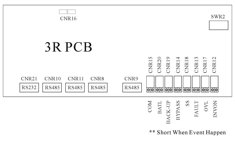
All interfaces are connected from 3R PCB. See the figure below.
6.1. Dry Contacts
8 terminals of dry contacts are provided. These terminals are normally open (non-conducting). When an event occurs, the terminal will close (conduct). Maximum contact rating is 16A/250VAC(16A/30VDC). The events are shown below.
INVON – Closed whenever the inverter is on, open when the inverter is off.
OVL – Closed whenever the UPS is overloaded.
FAULT – Closed when the UPS encounters a fault condition, such as high DC shutdown, short circuit, fuse/over-heat, overload shutdown, emergency stop, inverter abnormal, bypass on shutdown. The contact is latched until manual reset (off switch) or 30 seconds after the fault condition is removed.
SS – Closed when the inverter static switch is conducting, open when the reserve static switch is conducting (The two static switches will never conduct simultaneously).
BYPASS – Closed when the maintenance bypass breaker is closed, open when the breaker is opened.
BACK-UP – Closed when the inverter (running) is being backed up by the battery.
BATL – Closed when the inverter is using battery power and the batteries are about to be exhausted.
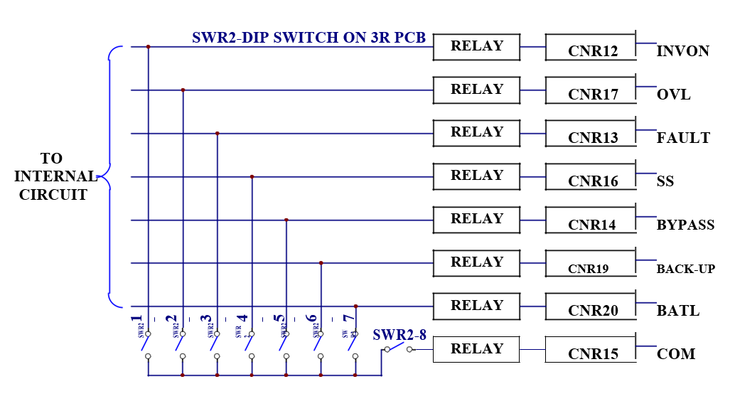
COM –This contact can be configured as the OR result of the signals described above. SWR2-1 (dip-switch pin 1) ~ SWR2-7 (dip-switch pin 7) can select one of the seven signals described above and SWR2-8 is the COM enable switch. Please refer to the dip-switch of SWR2 on the 3R PCB and the following examples and diagram.
Example 1:
If two contacts for BACK-UP are required. Switch on SWR2-6 & SWR2-8, then both CNR19 & CNR15 will close when the unit goes to back-up.
Example 2:
If one contact for OVL & FAULT is required. Switch on SWR2-2 & SWR2-3, then the CNR15 will close when either OVL or FAULT condition happens. Of course CNR17 will close when OVL happens and CNR13 will close when FAULT happens.
6.2. External Shutdown
2 pairs of terminals CNR 16 are provided for external shutdown. 10mA is needed for turning on the internal photo-coupler. The user can use this terminal to shutdown the UPS when emergency conditions occur, such as fire, short circuit etc.
6.3. DB9 Connection
Four RS-485 and one RS-232 are provided to communicate with more sophisticated (option) modules. Each connector is especially dedicated to one type of external module. The following are some connection examples of optional modules.
CNR21 (RS-232) Ù UPSCOM- Software for PC Monitoring、SNMP Card
CNR9 (RS-485) Ù DCMAN- Battery Monitoring Module CNR10 (RS-485) Ù UPSCAN- Remote Control Panel CNR12,13,14,15,17,18,19 (RS-485) Ù UPSCALL- Auto Dialing Module CNR11 Ù for transferring RS-485 into RS-232
7. OPTIONS
This chapter supplies a brief introduction to all the options that are available for the 3 Phase UPS. Similar products from other manufacturer will not fit into this UPS. Additionally, the installation of each option needs professional, trained personnel.
7.1. Battery Cabinet
The battery cabinet is designed with the same size and profile as the UPS. This is done for convenience of installation, and for an aesthetically appealing display when several cabinets of UPS and battery are aligned together. Also, structural strength is enhanced to endure vibration, shock, etc. during transportation. See the figure below.
BATTERY CABINET
7.2. Emergency Power Off Switch (EPO)
An emergency power off (EPO) switch is available as an option, installed outside but nearby the UPS, for stopping the UPS output in case of emergency, such as electrical shock, burning of the load or any emergency conditions where one wants to stop the AC output immediately. When the EPO switch button is pushed, the inverter immediately stops running, but the static switch remains tied to the inverter. Therefore there will be no AC supply at the output. This shutdown condition will be latched until it is manually reset by pressing the OFF (0) switch and inverter control switch (WX) simultaneously.
Therefore, please first switch off INVERTER ( push right & middle of inverter switch simultaneously) and then on INVERTER again (left & middle of inverter switch simultaneously) to restart the UPS after the EPO is triggered.
7.3. Remote Control Panel – UPSCAN™
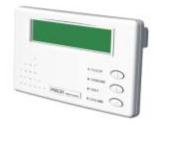
UPSCAN™, remote control panel, is a hand held display module with LCD (the same as the LCD of the UPS). It is used to switch, on or off, any or all of the UPS systems. When any UPS encounters an emergency condition, the system will warn the user immediately. All the UPS status, data or commands are transmitted to external modules through 4 RS-485 ports (for long distance communication under harsh environment).
UPSCAN™ can monitor 1 to 99 units of UPSs with DB9 connections in series from distance of up to 1000M.
7.4. Software for PC Monitoring – UPSCOM™
UPSCOM™ is a hardware/software combination installed on a PC to monitor multiple UPSs with DB9 connection in series. The connector on the UPS’s side is RS-485 (for long distance transmission); therefore an RS-485 Ù RS-232 adapter (hardware) is required to modify the signal. The software and hardware together form a package called UPSCOM™. See the UPSCOMTM specification for further information.
7.5. Auto Dialing Module – UPSCALL™
In case abnormal situations occur, UPSCALLTM will automatically dial specified phone numbers to inform management to take prompt action. The module, with built-in 23A12V battery, consumes power only when in the process of dialing so as to be operated under AC source failure. Furthermore, with functions of multiple phone number setting and dialing, UPSCALLTM has no need of dedicated lines, and can offer user a prompt and convenient way for monitoring the UPS. See the UPSCALLTM specification for further information.
7.6. Battery Monitoring Module – DCMAN™
DCMAN™ is an intelligent module for watching each individual battery in the battery bank in a simple and direct way. DCMAN™ can distinguish for repair the initially aged battery under safe conditions, thus prolonging the battery life expectancy. One module can monitor up to 64 pieces of 12V battery. DCMAN will sound an alarm in case of an abnormal situation, such as battery failure, cable abnormal disconnection, or if the remaining battery charge is less than the parameter set in the module. See the DCMAN™ specification for additional information.
8. REDUNDANCY
Redundancy can be roughly divided in two types: serial (hot standby) redundancy and parallel (active) redundancy. The UPS series adopts mainly serial redundancy.
8.1. Serial Redundancy
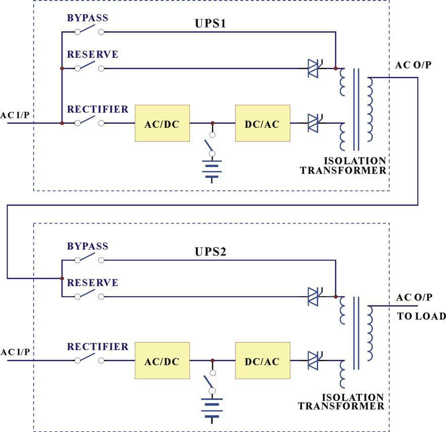
ONE TO ONE SERIAL REDUNDANCY
Serial (hot standby) redundancy consists of two UPS with one UPS’s (UPS1) connected to the reserve/bypass input of the other UPS (UPS2). See the above figure.
Both UPSs are running in normal mode under normal conditions. When one of them has a problem, the load will still have protection from the inverter and battery. If UPS1 fails and UPS2 is running normally, the load is unaffected, and supplied from UPS2. If UPS2 fails and UPS1 is running normally, UPS2 will transfer the load to UPS1 and the load will continue to be protected by the inverter and battery of UPS1. If both of them are running normally, UPS2 takes up all load and UPS1 bears no load. Therefore, UPS1 has a longer MTBF than UPS2 (can be interchanged after a period of time), and their MTBF multiplies to a very large MTBF.
This type of redundancy is employed most frequently. When mains fail, UPS2 is the first to contribute its battery to back-up the load. When UPS2’s batteries are exhausted, the load is transferred to UPS1. Therefore, this topology can make full use of the batteries of both units. Users get a system that has redundant protection and double the back-up time.
Another less expensive solution (see the figure below) is available if the load is separated. A user may intend to install two UPSs, each with the same power, and supplying half the load. A third UPS can be installed as backup to two main UPSs. It is statistically improbable that both main UPSs concurrently break down. Therefore, the third UPS can serve as a hot standby to two UPSs.
These topologies make full use of the resources to create the best protection and longest MTBF.
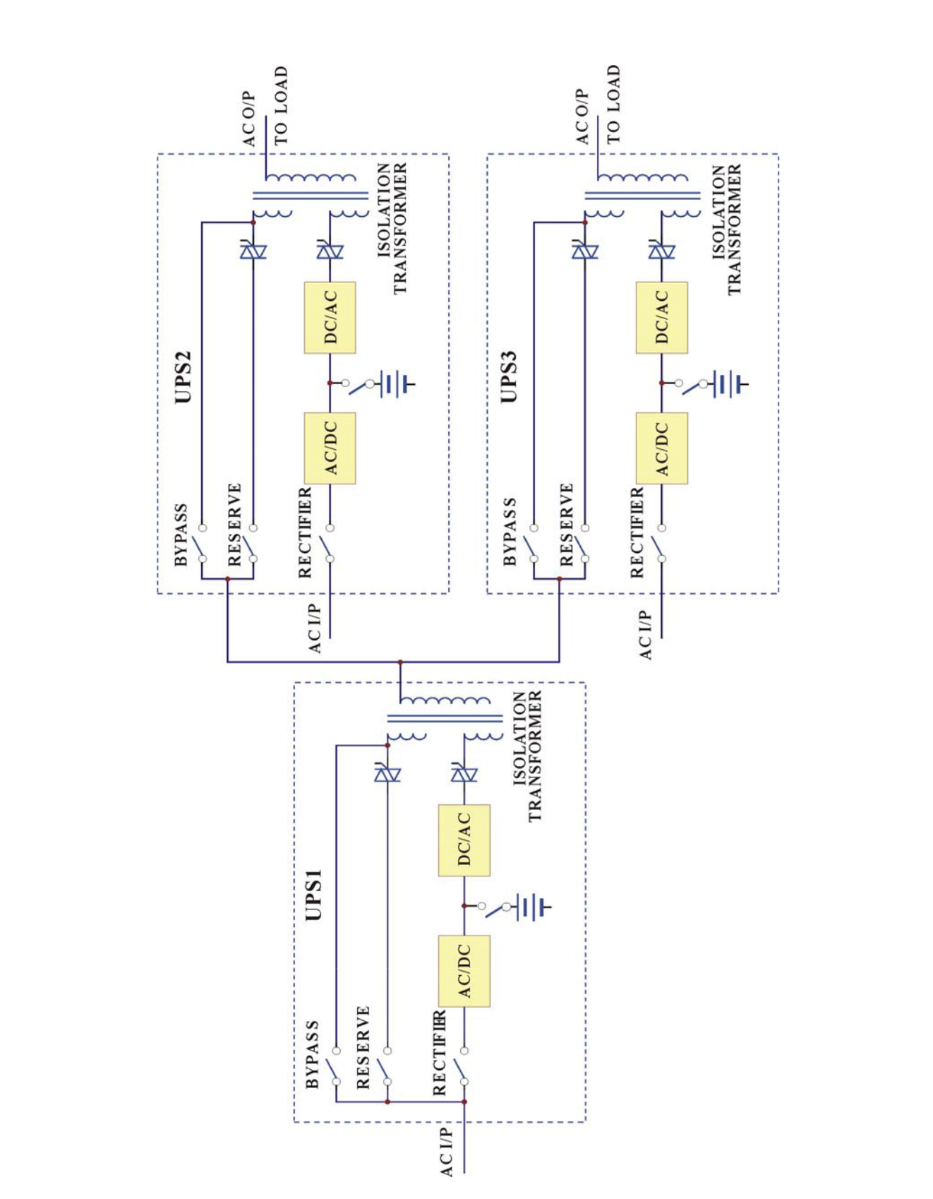
ONE TO TWO SERIAL REDUNDANCY
8.2. Parallel Redundancy
The parallel redundancy configuration, like below figure, is designed to increase both the capacity and reliability. And all the UPS are sharing with equal load.
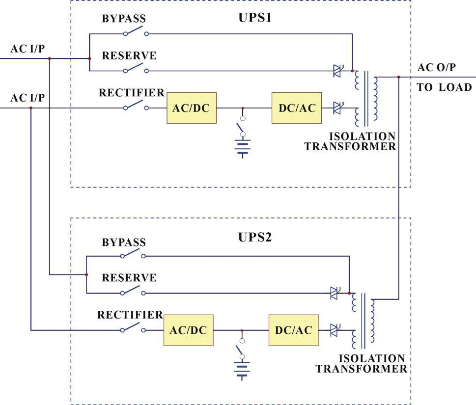
9. HELP
Followings are some abnormal situations frequently asked and common solution is offered for trouble-shooting.
| Abnormal | Description & Checkpoint | Solution | |
| (1) AC input | The rectifier breaker is not switch on. | Switch on the rectifier | |
| is correct, but | breaker. | ||
| rectifier does | |||
| The input voltage is not correct (out of | Connect the right AC | ||
| not operate | |||
| the normal range). | source. | ||
| and RECT AC | |||
| FAIL LED | |||
| The phase sequence of AC input is | Correct the R.S.T. phase | ||
| lights up. | |||
| incorrect, input rotation error, and the | sequence. Generally, to | ||
| LCD will display warning message | exchange any two phases | ||
| “RECT PHASE ERROR” in the | connection can solve this | ||
| STATUS/WARN menu (MAIN menu → | problem. | ||
| SELECT menu → STATUS/WARN | |||
| menu). ROTATION ERROR LED on | |||
| left side of the front panel will also | |||
| light. | |||
| If the abnormality cannot be corrected | Refer to PCB LED | ||
| when the solution actions have been | Detecting Guide and | ||
| taken. | check the 3C PCB. | ||
| (2) The UPS | The battery fuse (breaker/holder/dis- | Close the battery fuse | |
| shuts down | connector) has not been closed. | breaker/holder/dis- | |
| under AC | connector. | ||
| mains failure. | |||
| (3) No power | The reserve breaker has not been closed | Close the reserve breaker. | |
| supply for | (switched on). | ||
| UPS control | |||
| 3B PCB has problem. | Refer to PCB LED | ||
| circuit and | |||
| LCD cannot | Detecting Guide and | ||
| display. | check the 3B PCB. |
| Abnormal | Description & Checkpoint | Solution | |
| (4) The | There is external wiring error of R.S.T | Correct the external | |
| voltage | phase and N. G., instead of UPS unit | wiring system. | |
| difference | itself,. | ||
| between | |||
| NEUTRAL | |||
| and | |||
| GROUND has | |||
| become | |||
| abnormally | |||
| high. | |||
| (5) The | Other than INVERTER SS LED in left | Do trouble shooting | |
| inverter | side of the front panel, other LEDs still | according to the LED | |
| cannot start | illuminate. | instruction. | |
| up. | |||
| Switch on the inverter before DC bus | Refer to the switch on | ||
| has been established completely. | procedure. Close the | ||
| Normally, it takes around 30 seconds | reserve and rectifier | ||
| to establish the DC BUS once the | breakers and wait around | ||
| reserve and rectifier breakers are | 30 seconds or directly use | ||
| closed. | batteries to establish the | ||
| DC bus. | |||
| Bypass breaker has been closed | Open the bypass breaker. | ||
| (switched on). | |||
| The output is overloaded. The LCD | Decrease the load to | ||
| will display warning message ‘ XXX% | below the UPS’s rated | ||
| OVERLOAD’ in the STATUS/WARN | power. | ||
| menu (MAIN menu → SELECT menu | |||
| → STATUS/WARN menu). XXX% | |||
| OVERLOAD LED on left side of the | |||
| front panel and OVERLOAD LED on | |||
| right side will also light. | |||
| In P&P modules1, the temperature | Take out the P&P modules | ||
| sensor sockets on 3G PCB and hest | and connect them | ||
| sink are not connected properly. | properly. | ||
| WARNINGLED of FUSE/TEMP still | |||
| illuminate but LED in 3G PCB | |||
| doesn’t, indicating DC BUS may be | |||
| over 240VDC. |
| Abnormal | Description & Checkpoint | Solution | |
| (6) Fans do | The fuses positioned behind PCB | Replace the fuses or | |
| not work | holder have been blown or are not | install them properly. | |
| while UPS is | installed properly. | ||
| on. | |||
| Abnormal voltage output in R phase. | Refer to PCB LED | ||
| Detecting Guide and | |||
| check the 3T PCB of R | |||
| phase. | |||
| (7) The | Voltage limit function failure in the | Refer to PCB LED | |
| rectifier shunt | 3B, which contributes to the DC | Detecting Guide and | |
| down and | voltage, goes over 430V. | check the 3B PCB. | |
| HIGH DC | |||
| 3C PCB has problem. | Refer to PCB LED | ||
| LED is lit. | |||
| Detecting Guide and | |||
| check the 3C PCB. | |||
| (8) Abnormal | RESERVE AC FAIL LED lights up. | Check the reserve wiring | |
| voltage in | LCD menu also displays the abnormal | and connect with the | |
| reserve. | voltage in reserve. (REAL TIME | correct source. | |
| DATA menu → RESERVE DATA | |||
| menu). | |||
| Fuse has blown in 3A PCB | Replace the fuse. | ||
| If the abnormality cannot be corrected | Refer to PCB LED | ||
| after the solution actions have been | Detecting Guide and | ||
| taken. | check the 3A PCB. | ||
| (9) Abnormal | RESERVE FREQ FAIL LED lights up. | Check the reserve wiring | |
| frequency in | LCD menu also displays the abnormal | and connect with the | |
| reserve. | voltage in reserve. (REAL TIME | correct source. | |
| DATA menu → RESERVE DATA | |||
| menu). | |||
| Fuse has blown in 3A PCB | Replace the fuse. | ||
| If the abnormal cannot be corrected | Refer to PCB LED | ||
| after the solution actions have been | Detecting Guide and | ||
| taken. | check the 3A PCB. |
| Abnormal | Description & Checkpoint | Solution | |
| (10) The | Bypass breaker has been closed | Open the bypass breaker. | |
| inverter shuts | (switched on). | The inverter will restore | |
| down during | running automatically. | ||
| operation, | |||
| The output is short-circuited, including | Clear the short circuit at | ||
| while the | |||
| the load itself. | the output, then switch off | ||
| FAULT LED | |||
| the inverter. | |||
| lights and | |||
| buzzer beeps | Secondly, switch on once | ||
| continuously. | more to restart the | ||
| inverter. | |||
| The output is overloaded. The LCD | Decrease the load to under | ||
| will display warning message ‘ XXX% | the UPS’s rated power. | ||
| OVERLOAD’ in the STATUS/WARN | Then the inverter will | ||
| menu (MAIN menu → SELECT menu | restore running | ||
| → STATUS/WARN menu). XXX% | automatically. | ||
| OVERLOAD LED on left side of the | |||
| front panel and OVERLOAD LED on | |||
| right side will also light. | |||
| Heat Sink is over temperature. | Decrease the load to under | ||
| WARNING LED of FUSE/TEMP still | the UPS’s rated power, | ||
| illuminates. | then switch off the | ||
| inverter. Secondly, switch | |||
| on once more to restart | |||
| the inverter. | |||
| IBGT-protect fuse has blown in P&P | Take out the P&P module | ||
| module1 or IGBT damage. | and replace fuse or IGBT. | ||
| When in battery back-up mode, the | Within 30 minutes, the | ||
| inverter shuts down due to battery low | inverter will restore | ||
| (lower than 295VDC). | running automatically | ||
| once the AC main is back. | |||
| The Emergency Switch has been | Switch off the inverter | ||
| triggered. | first then on once more to | ||
| restart the inverter. |
| Abnormal | Description & Checkpoint | Solution | |
| (11) | DC BUS voltage becomes abnormal | Take out the P&P module | |
| Transferring | during transferring. DCV value can be | 2 and make sure the SCR | |
| failure | read in LCD menu. | drive connection is OK. | |
| between | |||
| 3P PCB has problem. | Refer to PCB LED | ||
| reserve and | |||
| Detecting Guide. Take out | |||
| inverter. | |||
| the P&P module 2 and | |||
| check the 3P PCB. | |||
| LED A4(OTF) in the 3A PCB lights. | Refer to PCB LED | ||
| Detecting Guide and | |||
| check the 3G PCB. | |||
| In P&P modules, the temperature | Take out the P&P module | ||
| sensor sockets on 3G/3P PCB and hest | and connect them | ||
| sink are not connected properly. | properly. | ||
| WARNING LED of FUSE/TEMP still | |||
| illuminates. | |||
| Phase sequence error of output | Change the transformer | ||
| transformer. | wiring. | ||
| If the abnormal cannot be improved as | Refer to PCB LED | ||
| the aforesaid solution action has been | Detecting Guide and | ||
| taken. | check the 3G and 3P PCB. | ||
| (12) Phase | The mimic output LED in the front | Make sure the signal | |
| lack when AC | panel blinks. | sockets in 3T PCB are | |
| output. | connected properly. | ||
| Fuse has blown in 3T PCB | Replace the fuse. | ||
| If the abnormal cannot be corrected | Refer to PCB LED | ||
| after the solution actions have been | Detecting Guide and | ||
| taken. | check the 3T PCB. | ||
| (13) The | Batteries become worn out or | Replace batteries. | |
| mimic battery | damaged. | ||
| LED in the | |||
| front panel | |||
| blinks. | |||
| Abnormal | Description & Checkpoint | Solution |
| (14) All LED in the front panel light up. | CPU inserting error in 3A or 3R PCB | Insert the CPU into correct socket |
| (15)Communication interface is not working properly. | Communication cables are connected improperly. | Correct the wiring. |
| Communication software is not installed successfully. | Reinstall the software. | |
| Communication port setup error. | Correct the setup. | |
| CPU inserting error in 3R PCB. | Insert the CPU into right socket. | |
| If the abnormal cannot be corrected after the solution actions have been taken. | Refer to PCB LED Detecting Guide and check the 3R PCB. | |
| (16) The inverter has been turned on but no action of inverter. | The inverter switches of & are not pressed simultaneously. | Try to press these two buttons simultaneously |
| PCB Connection is not good. | Refer to PCB LED Detecting Guide and check the connection of 3W PCB. |